The SAVARA project aims to leverage the concept of a choreography (or conversation) description to provide design-time and run-time governance of an SOA.
A Choreography provides the means to describe the service interactions between multiple parties from a global (or service neutral) perspective. This means that it is possible for an organisation to define how an end-to-end business process should function, regardless of whether orchestrated or peer-to-peer service collaboration will be used.
Although in simple situations, a BPEL process description (or BPMN process model) can provide a description of the interactions between multiple services, this only works where a single orchestrating process is in control. The benefit of the choreography description is that it can be used to provide a global view of a process across multiple orchestrated service domains.
This document will outline how the Choreography Description is being used as part of SAVARA to provide SOA governance capabilities for each phase of the SOA lifecycle.
When a validated design has been approved by the users, it can be used to generate an initial skeleton of the design and/or implementation for each service.
WS-CDL, or Web Service Choreography Description Language, is a candidate recommendation from W3C. Although associated with W3C and Web Services, it is important to begin by stating that the Choreography Description Language (CDL) is not web service specific.
More recently the BPMN standard, under the guidance of the OMG, has introduced its own Choreography Model to complement the previous Process and Collaboration Models.
The purpose of a Choreography is to enable the interactions between a collection of peer to peer services to be described from a neutral (or global) perspective. This is different to other standards, such as WS-BPEL, that describe interactions from a service specific viewpoint.
In essence a Choreography description declares roles which will pass messages between each other, called interactions. The interactions are ordered based on a number of structuring mechanism which enables loops, choices and parallelism to be described. In WS-CDL and BPMN2 Choreography, variables used for messages and for conditionals are all situated at roles. There is no shared state rather there is a precise description of the state at each role and a precise description of how these roles interact in order to reach some notion of common state in which information is exchanged and processed between them.
In Choreography we use interactions and these structuring mechanisms to describe the observable behaviour, the messages exchanges and the rules for those exchanges and any supporting observable state on which they depend, of a system.
Design-time governance is concerned with ensuring that the resulting system correctly implements requirements (whether functional or non-functional). A choreography description can be used to ensure that the implemented system meets the behavioural requirements.
The behavioural requirements can be captured as a collection of scenarios (e.g. sequence diagrams) with associated example messages. This enables an unambiguous representation of the business requirements to be stored in a machine processable form, which can subsequently be used to validate other phases of the SOA lifecycle.
Once the choreography description for the SOA has been defined, it can be validated against the scenarios, to ensure that the choreography correctly handles all of the business requirements.
Once the service enters the implementation phase, it is important to ensure that it continues to adhere to the design and therefore meets the business requirements. Currently this is achieved through the use of techniques such as continuous testing. However this is only as reliable as the quality of the unit tests that have been written.
When a 'structured' implementation language has been used, such as WS-BPEL, it will be possible to infer the behaviour of the service being implemented, to compare it against the choreography description.
Detecting incorrectly implemented behaviour at the earliest possible time saves on downstream costs associated with finding and fixing errors. By using static validation against the original design, it ensures that the implemented service will deliver its expected behaviour first time. This is important in building large scale SOAs where different services may be implemented in different locations.
There are two other areas where a choreography description can be used as part of design-time governance, that are not currently implemented in SAVARA:
Service lookup – the choreography description can be used to determine if a service already exists in the Service Repository that meets the appropriate behavioural requirements.
Service unit testing - this can be achieved using the scenarios originally specified to document the behavioural requirements. Rather than develop an independent source of test data, the scenarios can be used to validate the sequence of messages sent to, and received from, a service, as well as validating the contents of the messages returned from the service under test.
Runtime governance ensures that the SOA executes as expected according to predefined policies. In this context, a choreography description can be used in two ways.
The choreography description represents the interactions between multiple services to deliver a business goal. To validate the behaviour of each individual service, within the choreography description, the behaviour of each service can be derived from the choreography.
The derived behaviour (or “endpoint projection”) of a service can be used within a 'service validator' to monitor the inbound and outbound messages for the service, to ensure they conform to the expected behaviour. If an invalid message is detected, it would be possible to block it, to prevent it from causing subsequent problems in downstream systems. The error can also be reported to a central management capability.
The SAVARA runtime governance infrastructure will provide the ability to configure service validators to monitor the behaviour of individual services.
Validating each service locally can enable errors to be detected quickly, and the effects of the error prevented from contaminating other systems by blocking the erroneous messages.
However local service specific validation may not be adequate to identify errors that would affect the end-to-end business process. Therefore the message activity at each service validator can be reported to a central 'process correlation engine' which can reconstitute a global view of the business transaction, and determine if it matches the expected behaviour as defined in the choreography description.
The benefit of a correlated global view of the distributed business transaction is that it can be further analysed to ensure other governance polices have been followed – e.g. SLAs.
A scenario is essential a representation of a particular path through a business process.
Business processes usually have number paths that can be taken during a transaction. A simple example is when purchasing some goods, where one scenario maybe that the customer successfully completes their purchase, after receiving an appropriate credit rating. Another scenario may be that the customer has a bad credit rating and therefore the business transaction must reject the customer's purchase request.
In most business transactions there will be many different variations that could occur, and by defining these scenarios it is possible for business stakeholders to clearly define their needs (i.e. requirements), and for those scenarios to be used in subsequent phases of the software development lifecycle to ensure the system being built meets those needs.
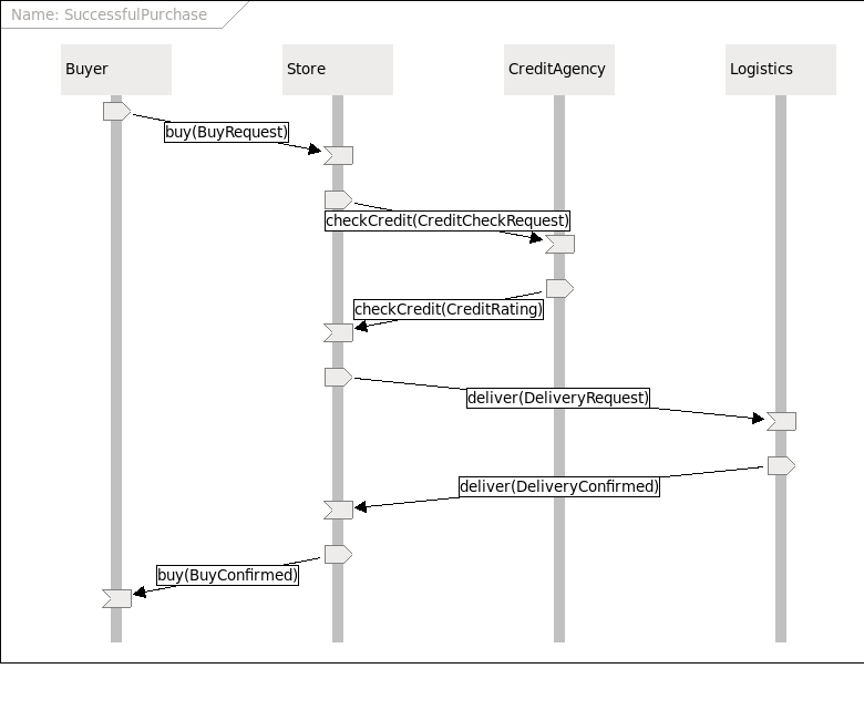
An example of a scenario representing a successful purchase is:
After creating an Eclipse project, and optionally a sub-folder to contain the scenarios being created, select the "New->Other..." menu item on the context menu for the project or folder in which the scenario be created. This will show the following dialog:
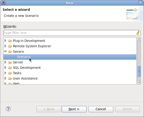
Select the Savara->Scenario item and then press the Next button, when you will be requested to enter the name of the scenario file, and then press the Finish button.
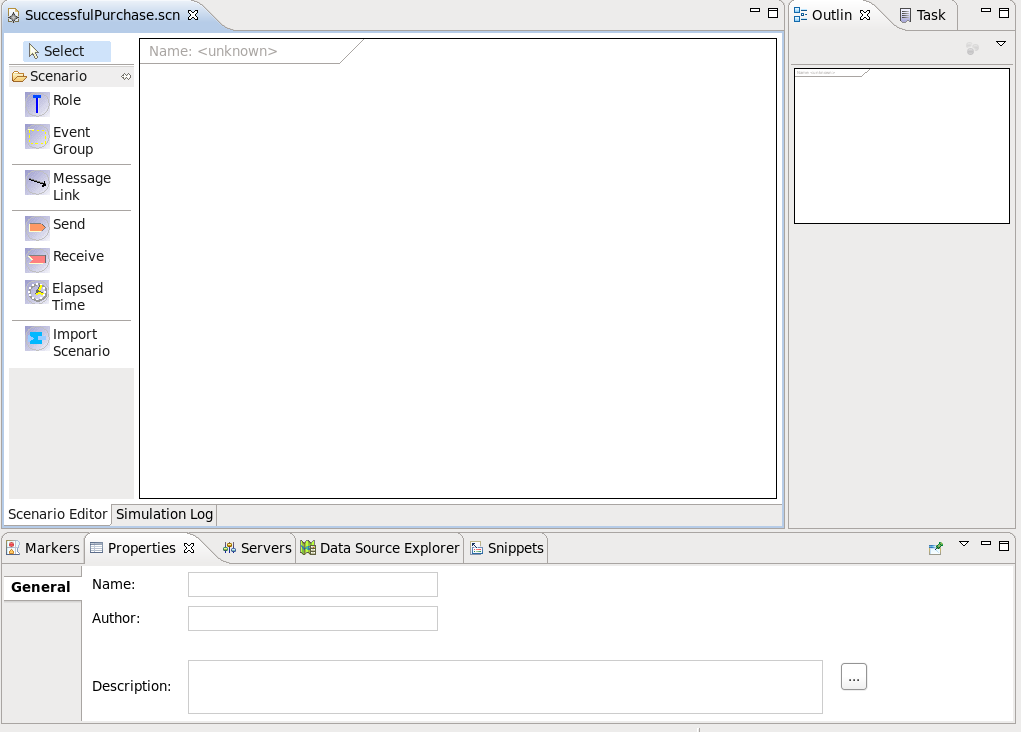
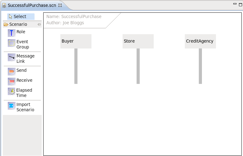
When the scenario is first created, it will have a blank canvas. If the Properties view is selected (at the bottom of the Eclipse window), and then the canvas is selected, the Properties view will show the properties associated with the scenario, i.e. name, author and description. These fields should be complete to provide a clear identification of the scenario, its owner and the details of what use case it represents in the context of the system being built.
A Role is a participant within the scenario. It represents an entity that is actively involved in performing tasks to help achieve a particular business goal.
We currently assume that there is a one-to-one mapping between a role and a service being implemented, although this will not always be the case. On some occasions a role may begin as a high level concept, which may evolve through the design process to become multiple services, possibly implemented by a single top level composite service associated with the role. It is also possible that a role may represent a human (i.e. manual) task.
To add a new role to the scenario, simply select the Role item from the left hand palette and click on the canvas. The role is displayed as a vertical line, with a box at the top containing the role name (which is "<unknown>" until a valid value is defined).
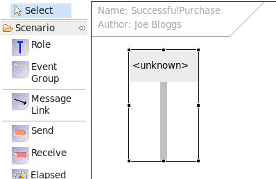
When the role is selected, the Properties view will show the property fields appropriate for this item. At this point, the role should be named. For example, in our example scenario we will create three roles, Buyer, Store and CreditAgency:
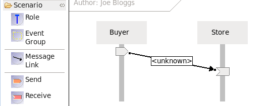
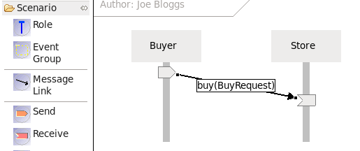
An interaction represents the exchanging of a message from one role to another role(s).
This is achieve by dragging a link between the 'originating' (or 'source') role to the 'destination' (or 'target') role. This will cause 'send' and 'receive' message events to be added to the source and target roles, with a link between drawn between them.
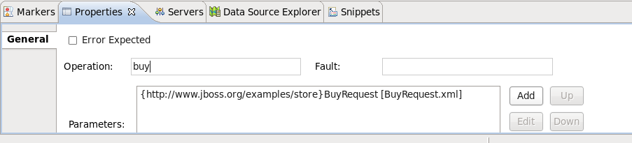
While the link is selected, go to the Properties view to set the relevant properties for the message.
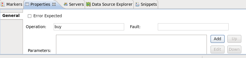
The "Error Expected" property is a checkbox that can be used to indicate that this message is expected to be incorrect when used for simulating or testing against other artifacts.
The "Operation" field represents the name of the operation being performed. In cases where the target architecture is message oriented, this may not seem necessary, however it can be useful to clarify the purpose of the interaction.
The optional "Fault" field is used to provide a fault name for the interaction, in situations where the message exchange represents a fault response.
The "Parameters" list represents the one or more pieces of information that should be exchanged with the message. Pressing the 'Add' button will show another dialog window:
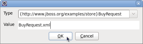
The "Type" field represents a fully qualified type name. The value within the curly braces defines the namespace, and the remaining text is the 'local part'.
The "Value" field represents a path to the file containing the example message value. The path can define a relative path, as in the image above, from the scenarios location. So this example indicates that the message value file ( BuyRequest.xml ) is in the same folder as the scenario file that is referencing it.
Once the parameter has been defined, it will be displayed in the parameters list as above and the text associated with the message link will be updated to summarize the information.
It is also possible to select the individual send and/or receive message events from the palette and attach them to the appropriate roles, with or without a link to connect them. For example, if a 'send message event' is placed on a Role, with the associated message information, this will indicate that the role sends a message but the intended recipient does not get it for some reason.
This is an example of where we want to represent an invalid (or negative) use case. Although this may seem counter intuitive, it can be useful to be able to specify anti use cases, as a way to document situations that we don't want to be implemented. Through the use of the 'Error Expected' field (associated with the Message Link properties) it is also possible to identify which parts of these negative scenarios should observe errors, and therefore can be used for automated testing.
As previously described, scenarios allow us to represent different paths that may occur through a business process.
Although most of these paths will be based on actions taken by the various roles involved in the scenario, occasionally scenarios also need to be able to indicate what should happen when no action occurs - i.e. a 'time out' situation.
As we are building up our scenario, if appropriate, we can introduce an 'elapsed time' event into the scenario. So if we start with an interaction to the CreditAgency, e.g.
We then want to be able to define a scenario to represent the case where the CreditAgency does not respond within a certain time period. To add an 'elapsed time' event, simply select the "Elapsed Time" icon from the palette and select the vertical location on the diagram where the event should be added. It will introduce a region horizontally across all roles.
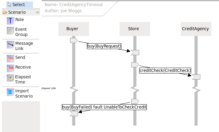
Figure 2.12. Scenario representing the case where a timeout occurs, and the behaviour that should follow
This can be used to document that the maximum timeout should be 2 minutes (120 seconds), and also used during simulation/service testing to ensure the implementation correctly handles the timeout.
Scenarios, like any other model, can benefit from reuse.
This section shows how scenarios can be composed, to allow common "sub" scenarios to be reused as part of high level scenarios. The benefit of this approach is the maintenance of scenarios, where a common sequence of messages exchanges between the same set of roles, is relevant to many use cases. When it becomes necessary to make a change to this common scenario, it only needs to be performed in one location to be applicable to all use cases.
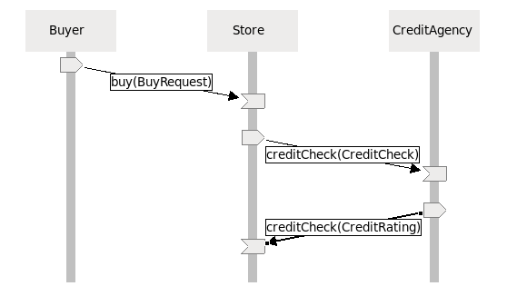
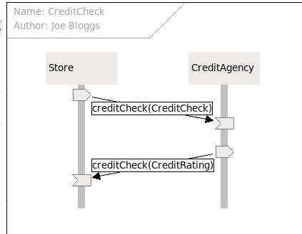
The following is a scenario related to performing the credit check:
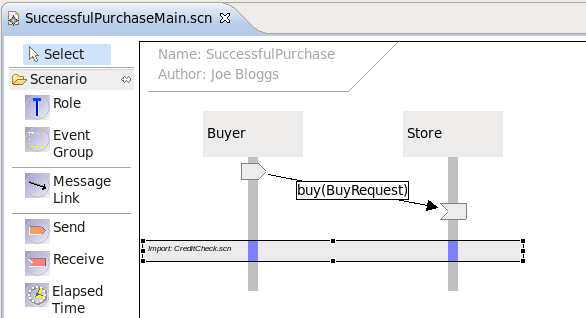
This can then be used within a higher level version of the SuccessfulPurchase scenario:
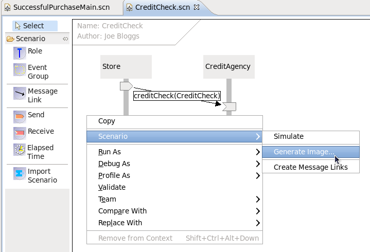
The Scenario diagram can be generated as an image for inclusion in documents or simply to be printed.
To generate the image, select the "Scenario->Generate Image" menu item from the context menu associated with the scenario background:
This will display a file dialog to select the name, type (e.g. bmp, png, jpeg, etc) and location for the generated image file.
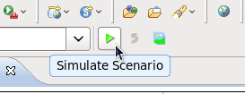
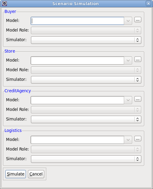
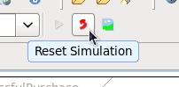
The scenario simulation is triggered either using the button on the toolbar, or the "Scenario->Simulate" menu item on the context menu associated with the diagram background:
This will display a dialog window to capture information used to simulate each of the roles defined in the scenario, e.g.
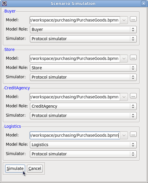
The next step is to associate a model with one of the roles. This is achieved by selecting the "..." button next to the model field, which allows the user to select the model file. A model file can be anything - if the file is a supported representation, then its selection will result in the "Model Role" and "Simulator" combo boxes being populated with valid values.
The "Model Role" field displays a list of roles that are derived from the selected model. This enables the role name defined in the scenario (shown in blue associated with the border), to be associated with the role within the model.
The "Simulator" field displays the list of simulators that can be used to validate the scenario against the model. Some model types may have more than one simulator implementation - this will be discussed more in subsequent sections. When a new simulator is selected, then the "Model Role" list will be updated based on the list of model roles determined by that simulator.
Once the first model has been selected, the user will be prompted to ask whether the same model should be used for all roles in the scenario.
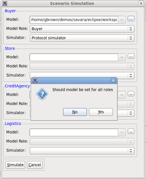
If the model that was selected was specific to the role (i.e. it represented an implementation just relevant to the particular role), then press the No button. However if the model is associated with more than one role in the scenario (i.e. a choreography), then pressing the 'Yes' button populates the simulation dialog, using the "best guess" to select the model role relevant for the scenario role.
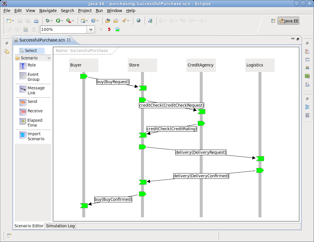
When the "Simulate" button is pressed, then message events (associated with the specific roles) in the scenario are simulated against the models specified in the dialog. If the message event is valid, its node will be displayed in green. If however the event is unexpected, then it will be displayed in red. When this occurs, either select the message link or particular red node, and then pick the "Simulation Log" tab at the bottom, to see log information returned from the simulator regarding the erroneous events.
NOTE: If a scenario 'message event' has been marked as 'Error Expected', then it will be displayed with a red border - but when simulated, the color within the message event node will be green if the node failed as expected, but red if the event did not generated an error.
Finally the simulation can be reset,
A Choreography represents the description of how multiple participants (or roles) interact to achieve a goal.
In a Service Oriented Architecture context, it provides a service neutral view of a complete architecture, documenting how the services should communicate with each other in a peer-to-peer manner. This description can be used to understand the complete process at a higher level, and then used to generate initial template service designs (or implementations) for each of the participants within the choreography.
The BPMN standard has been around for some time, although it was focused on providing a standard notation for describing business processes.
In 2011 a major new version of the standard was created under the OMG with the following goals:
provide a standard meta-model, to support interchange
define execution semantics for the process model
add a choreography model to the existing process and collaboration models
The BPMN2 Choreography can be created using the Eclipse BPMN2 modeller that is bundled with the Savara Eclipse tooling, as well as being available from: http://eclipse.org/projects/project.php?id=soa.bpmn2-modeler
To create a BPMN2 Choreography, select the “New->Other...” menu item on the context menu for the project or folder that will contain the file, which will display the following dialog:
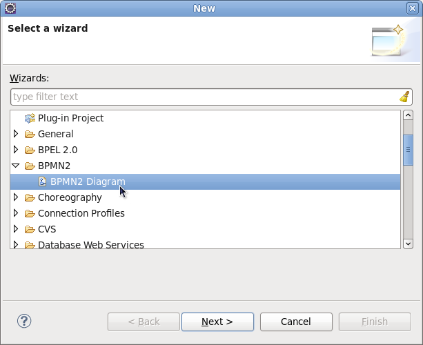
Select the “BPMN2 Diagram” under the BPMN2 category and press the Next button.
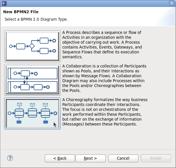
As we wish to create a choreography, you should now select the bottom button and press the Next button.
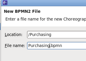
The final step in creating the diagram is to name it, and then press the Finish button.
Once the diagram has been created, it is useful to establish any XSD schemas (with their namespaces and prefixes) before making use of them when building the diagram.
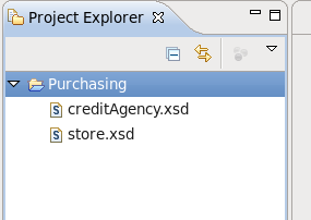
In this example, we copy two existing schema files into the newly created project.
NOTE: Normally this information can be established on the fly when specifying the item definition, but currently does not work, so needs to be done as a separate step. So could possibly remove this step when this feature is available again.
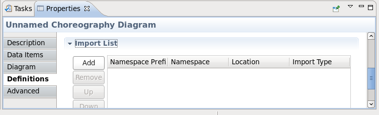
Open the Properties view and select the diagram background. Then select the 'Definitions' tab (as shown in the image) and scroll down to the Import List section. Pressing the 'Add' button will show the following dialog:
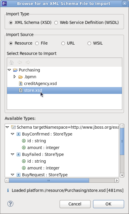
Locate the XSD schema file(s) and press the OK button. Although in this case we have two schemas within the project, it is possible for the schemas to be located using a few different mechanisms.
NOTE: URL location does not seem to work currently – and it would also be useful to define an import for a namespace/prefix that does not have an associated schema, as the location is optional.
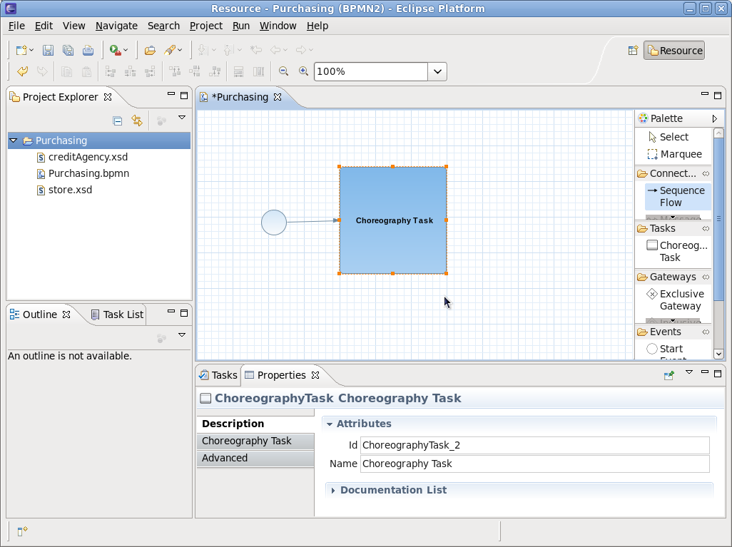
When a Choreography Diagram is initially created, it will create a default Choreography Task. It is possible to simply change this information as the starting point for your diagram, but for the purposes of this article we will create a choreography task from scratch – so select this default choreography task and delete it.
Components to be included in the Choreography Diagram are provided in the palette on the right hand side of the canvas. We initially want to start the diagram with a “Start Event”, a “Choreography Task” and a “Sequence Flow” to connect the two. This should then look like this....
The Properties view will show the details for the newly create Choreography Task, allowing you to change its name to something that reflects what it represents, e.g. “Submit Purchase Order”.

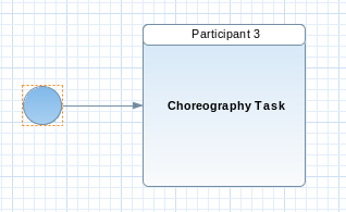
The next step is to establish the Participants that will be performing the interaction associated with the Choreography Task. As shown in the diagram, the Choreography Task has a short cut button (also available via its context menu) to add a participant.
When this button is pressed, it will add a new participant to the task, or if available, also present a list of existing participants that can be selected. The first participant added to the choreography task will be considered the 'initiating participant', which means it will send the message. If two messages are associated with the same choreography task (e.g. representing a request/response pattern), then the initiator sends the request, and the other participant would return the response. In general, only associate two messages with a choreography task if the associated 'operation' will only have the single response type. If it has multiple response types (e.g. one normal and one or more faults), then separate choreography tasks should be used – as will be seen later in the purchasing example.
When the participant band has been added to the choreography task, it can be selected to focus the Properties view on its properties. The name can then be changed to something more meaningful, for example Buyer. The following image shows the task after both participants have been added and their names changed.
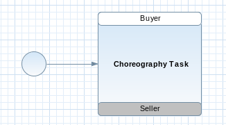
Figure 3.10. Participants given names using the Properties view when focusing on the participant band
Now that we have defined the choreography task to represent an interaction from the Buyer to the Seller, we now need to describe the message that will be passed between them.
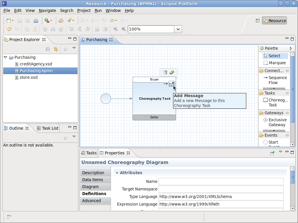
As with adding participants, there is a short cut button (and context menu item) for adding a message, associated with the participant band that is sending the message. So in the image above, adding a message to the Buyer would define the request, as the Buyer is the initiator for this task (denoted by its white background).
As with the 'Add Participant' action, if there are existing message definitions, then these will be presented to the user to enable them to select a previously defined message. Otherwise a message icon will simply be added.
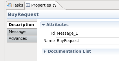
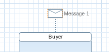
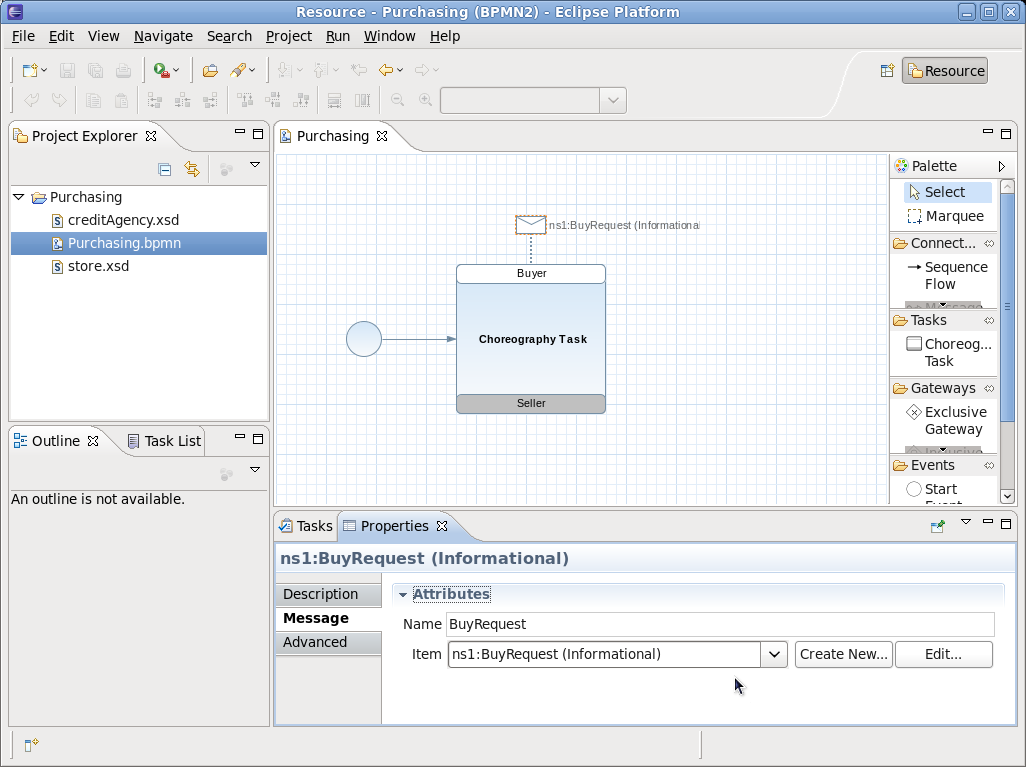
The user can now select this message 'envelope' to view its properties and set its name, e.g. “BuyRequest”.
However the BuyRequest name is only a logical name, it does not define the details of the message structure. This is ok when we are simply sketching the high level representation of a choreography, but to enable the choreography to represent concrete details, we need to associate the message with an item definition.
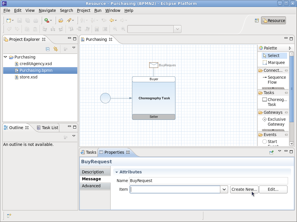
In the Properties view associated with the selected message there is an 'Item' field. This allows the user to select a previously defined message type (e.g. from an imported XSD schema), or if an appropriate entry does not exist, then we can press the 'Create New' button.
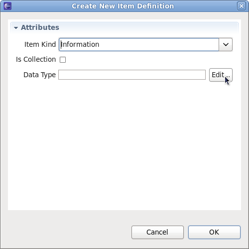
The 'Item Kind' field will always be 'Information', unless defining some abstract choreography describing how physical items are exchanged. The 'Data Type' field references the detailed message schema type. To set the field, press the 'Edit...' button and set the value:
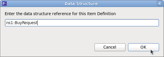
NOTE: Currently this only enables a free format string value to be defined – but should bring up the import dialog and enable the user to select a specific type, creating the import entry on the fly if necessary.
Now that the message details have been provided, the diagram displays that information in place of the logical message name.
NOTE: Currently does not actively update after this information is set – or when the message name is changed (when no item definition set).
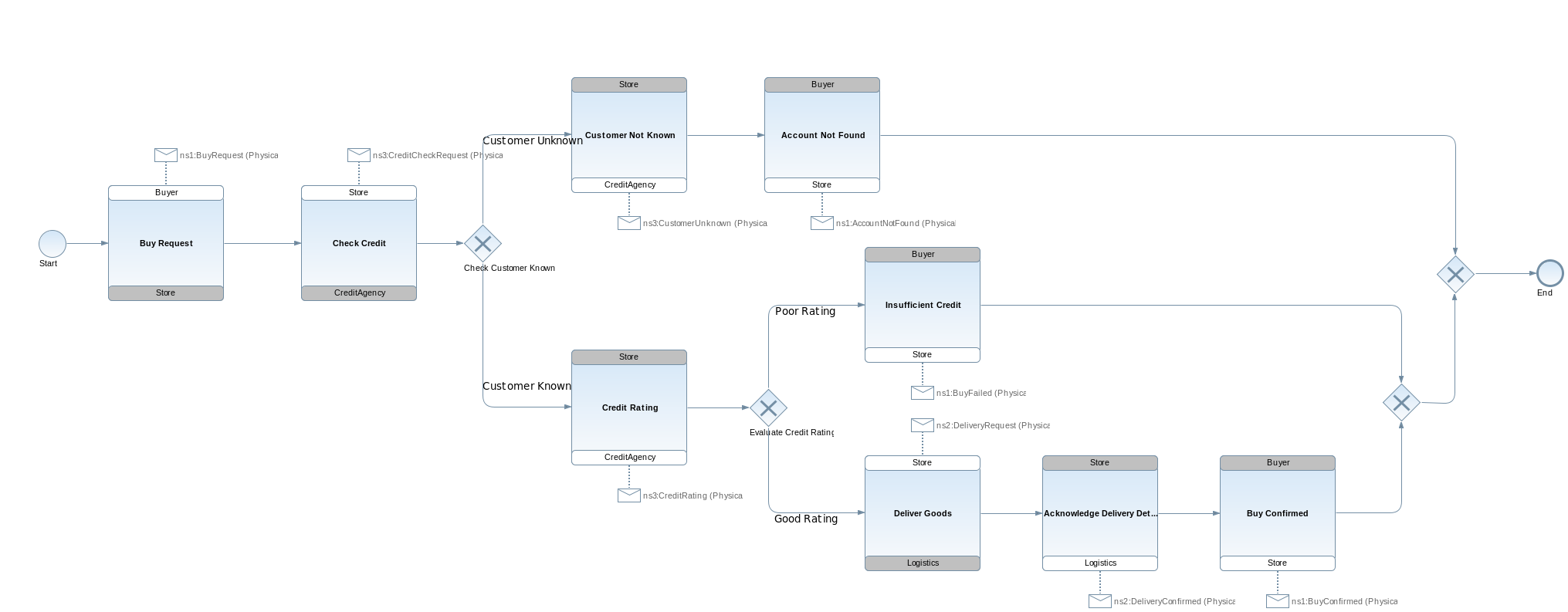
Using the same steps as defined above, each of the choreography tasks can be created, and with a couple of decision points we end up with the following business process.....
NOTES: Currently shows item definition kind as 'physical' – default is 'information'.
Although the choreography diagram (and underling model) now shows how messages are exchanged by participants in the choreography, these exchanges have not been defined in an SOA context, based on service interfaces. Therefore we also need to define (within the model) how these message exchanges are grouped into message exchange patterns (MEP) on interfaces associated with the participants.
Although this can be achieved by adding Interface and Operation components within the model, and establishing the appropriate associations from the participants to the interfaces, there is a short cut that will derive this information from the interactions in the model.
However before invoking this utility, we have one final step that needs to be done. In the preceding sections you have seen how to create messages and exchange them between participants as part of a Choreography Task. Although this is adequate information from a message passing perspective, as it defines a reference to the specific message schema that is used, it does not indicate whether the message exchange represents a fault associated with a preceding request.
Therefore it is necessary to distinguish whether a particular message type is actually a fault (or error), to enable the service interface derivation to correctly distinguish between normal and fault responses in a service operation.
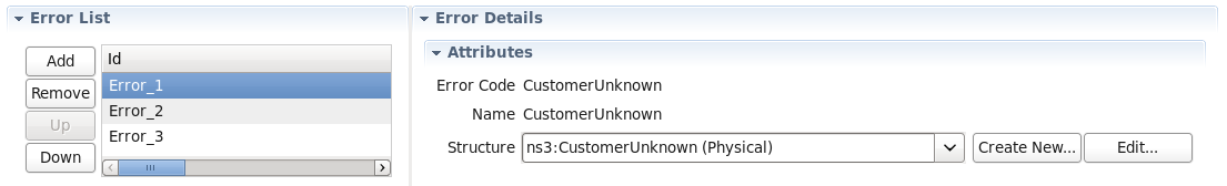
For each message type that needs to be highlighted as a fault, we need to create an Error component that references the same item definition. This Error component will essentially define the fault code for the fault, which will be used when constructing the RPC operation signature.
Select the Data Items tab, from the Properties associated with the diagram canvas, and expand the Error List :
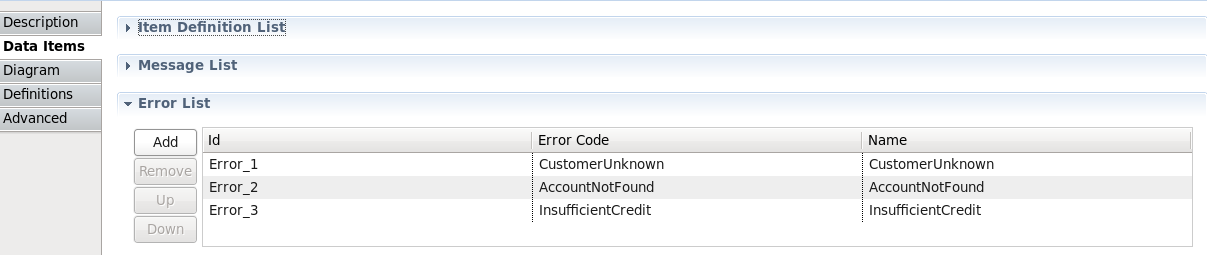
Using the 'Add' button, create a new entry and configure its details to reference the required item definition (representing the message schema) and error code:
Once all of the required Error components have been created and configured, then select the " Savara->BPMN2->Add Service Interfaces " menu item, associated with the BPMN2 choreography file, to create the appropriate interfaces and establish the necessary relationships.
The Choreography represents an overall description of the architecture intended to support a set of scenarios that define the business requirements.
Therefore, to ensure that the choreography correctly reflects those business requirements, it is import that we can verify the choreography against those scenarios.
As described in the previous Scenarios chapter, each scenario can be simulated against the choreography, to statically verify that the choreography addresses all of the use cases outlined in the scenarios.Once the choreography successfully verifies against each of the scenarios, it can then be deemed to represent the business requirements, and then be used to generate further service related artifacts.
The Savara Eclipse tooling includes the ability to generate contracts from source models. These models can vary, including (currently) choreographies and BPEL process definitions.
Select the "Savara->Generate->Contract" menu item associated with the context menu of the source model. For example,
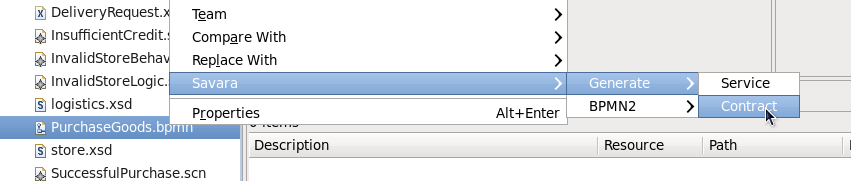
This will display a dialog window to allow the user to select how each role, identified within the source model, should be generated as a service contract:
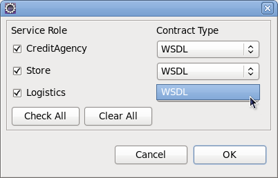
Figure 4.2. Dialog for specifying the service contract information for each role in the source model
The "Service Role" check box is used to indicate whether that role, within the source model, should result in a service contract being created.
The "Contract Type" field displays a list of contract generation types. This list will be dependent upon the source model type, and so will not be discussed in detail here.
When the OK button is pressed, each of the contracts for the enabled roles will be created with their relevant artifacts, within the current Eclipse project containing the source model.
The Savara Eclipse tooling includes the ability to generate services from source models. These models can vary, including (currently) choreographies and BPEL process definitions.
Select the "Savara->Generate->Service" menu item associated with the context menu of the source model. For example,
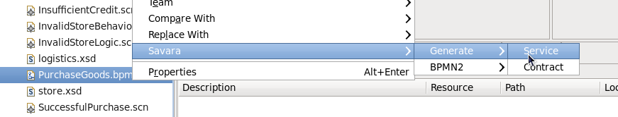
This will display a dialog window to allow the user to select how each role, identified within the source model, should be generated as a service design or implementation:
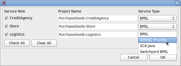
Figure 5.2. Dialog for specifying the service generation information information for each role in the source model
The "Service Role" check box is used to indicate whether that role, within the source model, should result in a service being created.
The "Project Name" field is used to enter the name of the project that will be generated. The project name is constructed from a combination of the model name and the role. If the project already exists, then the background of this field will be red, and the OK button will be disabled until either the service role checkbox for that role is unchecked, or the project name changed.
The "Service Type" field displays a list of service generation types. This list will be dependent upon the source model type, and so will not be discussed in detail here. The particular structure of each generated project will be dependent upon the service type selected. Some of these service types will relate to implementation technologies (e.g. SCA Java and BPEL), while others may be used to represent a service design (e.g. BPMN2 Process - although a BPMN2 Process can also evolve into an executable implementation).
When the OK button is pressed, each of the projects for the enabled roles will be created with their relevant artifacts.
NOTE: The list of target 'service types' is not related to the source model type. So (for example) if the source model is a BPEL process definition, then it is still possible that BPEL will be offered as a target service type. Although this may seem redundant, it can offer the opportunity to generate a abstract skeleton (observable behavior) version of a fully implemented executable BPEL process.
A Service Design or Implementation can be verified in two ways.
For service designs, which have no executable semantics (i.e. cannot be executed), or implementations where no simulator exists that can perform dynamic verification, it may be possible to simulate valid behavior (as defined by a set of scenarios) against the protocol derived from the service design/implementation.
This ensures that the design or implementation has the correct communications structure to be able to interact with other services (whether consumers or other producers).
For example, a scenario can be simulated against a BPEL process definition (and in the near future a BPMN2 process model) to determine whether they have the correct communication structure, even before they contain enough details to be executed.
Where a simulator exists associated with the service implementation technology, it is possible to replay the message events defined in the scenarios against an executing version of the service implementation, to ensure that a real service instance handles the scenario correctly.
For example, a scenario can be simulated against a SCA composite definition. (Switchyard services will be supported in the near future).