- 1. JBoss BPEL project Overview
- 2. Tasks
- 3. Reference
- 4. Troubleshooting
- 5. Summary
JBoss BPEL is based on WS-BPEL 2.0, and provides a way to create, edit, validate and deploy BPEL files to JBoss BPEL runtime. It is based on Eclipse BPEL project.
It improves the Eclipse BPEL project in the following ways:
Implements close integration with JBoss BPEL runtime, and adds a new project type for the deployment to the JBoss BPEL runtime.
Supports two deployment methods. The first method is to deploy a BPEL project directly to the JBoss BPEL runtime. The second method is to deploy BPEL files in JBoss ESB project to the JBoss BPEL runtime.
Enhances the BPEL validator and improves the quality of the Eclipse BPEL editor.
WS-BPEL 2.0 stands for Web Service Business Process Execution Language. Like EAI, BPEL is an XML-based language, but BPEL is more specific and targeted. BPEL is used by developers to join sometimes disparate functions into an integrated process, resulting in a seamless use of the Internet to conduct business transactions ranging from simple money exchanges to complex calculations and asset reallocation.
The table below lists the main features of the JBoss BPEL editor:
Table 1.1. Key Functionality for JBoss BPEL editor project
| Feature | Benefit |
|---|---|
|
WS-BPEL 2.0 support |
JBoss BPEL project supports the most recent WS-BPEL 2.0 specifications. |
|
Close integration with JBoss BPEL runtime |
There are two methods to deploy BPEL files to JBoss BPEL runtime. The user can deploy a BPEL project as a whole and can deploy BPEL files in a JBoss ESB project to the JBoss BPEL runtime. |
|
BPEL file editor |
The editor can be used separately to edit a BPEL file. |
|
BPEL file validator |
The validator displays a list of BPEL file errors. |
In this chapter we describe the necessary steps to create a new BPEL project and edit the BPEL files. You can get the example source code from riftsaw/samples/quickstart/hello_world. In this guide we will create a simple echo example, used to respond to a message with a modified version of the request message.
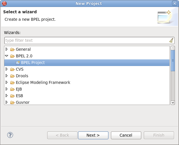
The first step is to create a BPEL project.
Create the project by selecting → → → → from the menu bar. Then click the button.
On this page of the New BPEL Project Wizard enter a project name in the Project Name field, e.g. enter HelloWorld.
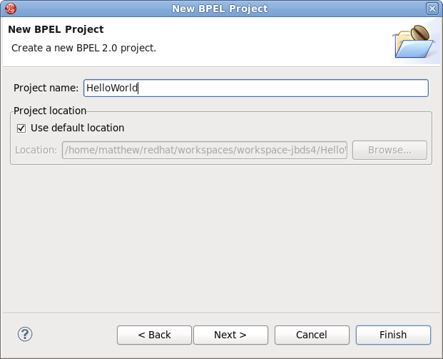
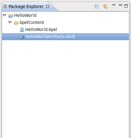
Click the button. So you have created the BPEL project named HelloWorld. Its structure is like this:
Now you should create a BPEL process. You can create it by selecting → → → → .
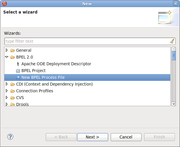
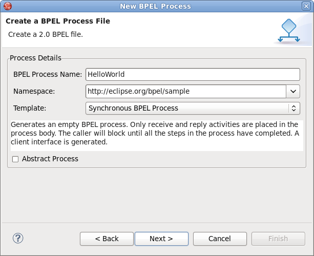
Click the button. Enter the following information:
Table 2.1. Fields and values
| Field | Value |
|---|---|
|
BPEL Process Name |
Enter a process name. For example, HelloWorld. |
|
Namespace |
Enter or select a namespace for the BPEL process. |
|
Template |
Select the appropriate template for the BPEL process. When you select the template, you will see the information about the template below on the page. In this case you should select Synchronous BPEL Process. |
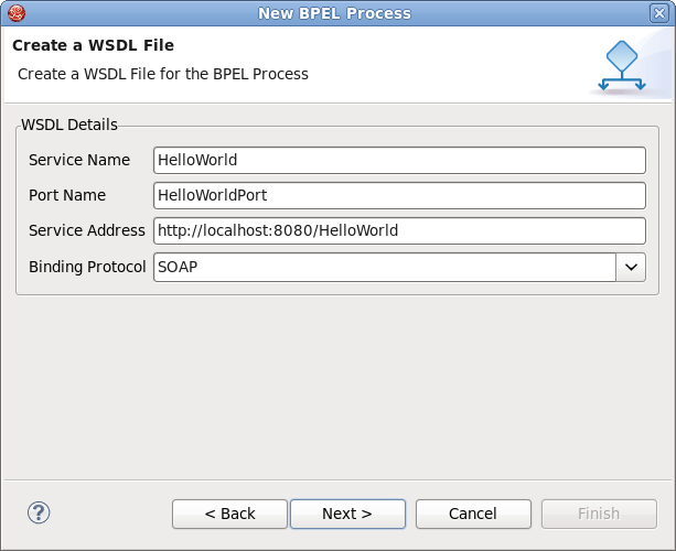
Click the button. On the second page, you can customize your WSDL service details. Enter the following information:
Table 2.2. Fields and values
| Field | Value |
|---|---|
|
Service Name |
A wsdl service name for the BPEL process. The default value is HelloWorld. |
|
Port Name |
A wsdl port name for the BPEL process. The default value is HelloWorldPort. |
|
Service Address |
An address of the WSDL service for the BPEL process. The default value is http://localhost:8080/HelloWorld. |
|
Binding Protocol |
The binding protocol that you use in the wsdl. You can choose SOAP or HTTP. The default value is SOAP. |
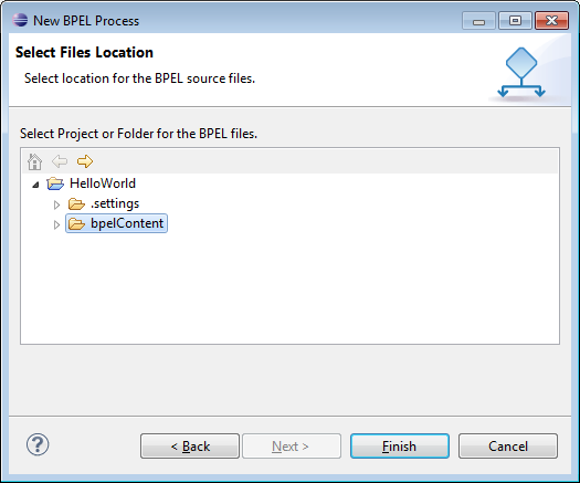
Click the button. On the third page, you can select a folder for the process file from the projects in your workspace. If a folder is not selected, the default folder HelloWorld/bpelContent will be used. Click the button.
Note
All of your files that are used in your BPEL project must be under the bpelContent folder of a BPEL project. Only in this case these files can be deployed to JBoss server.
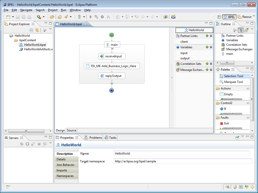
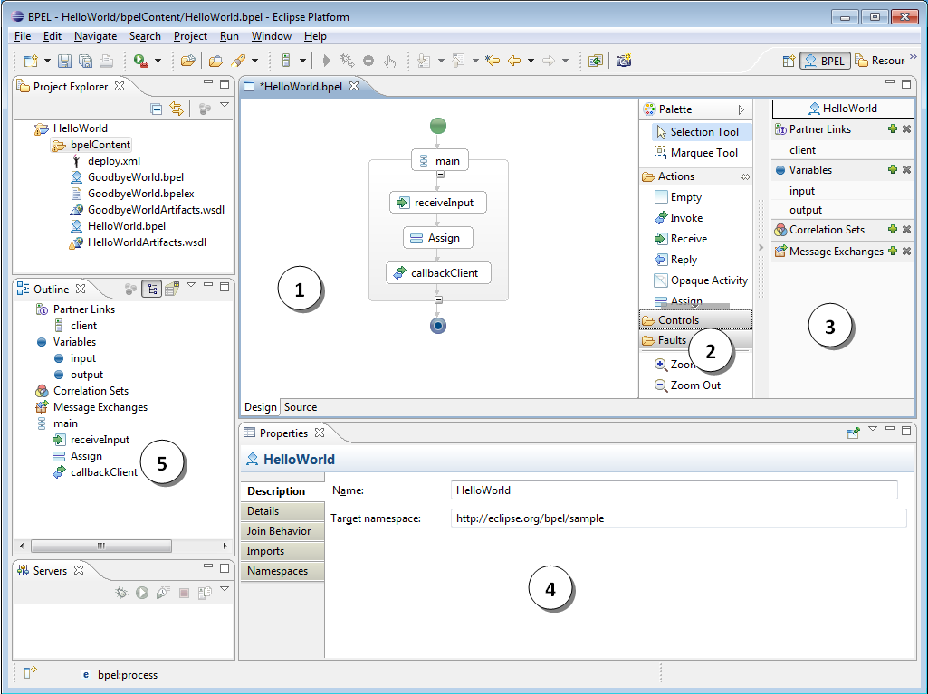
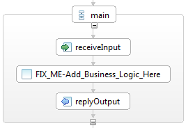
This will create a simple BPEL process as shown in the image below.
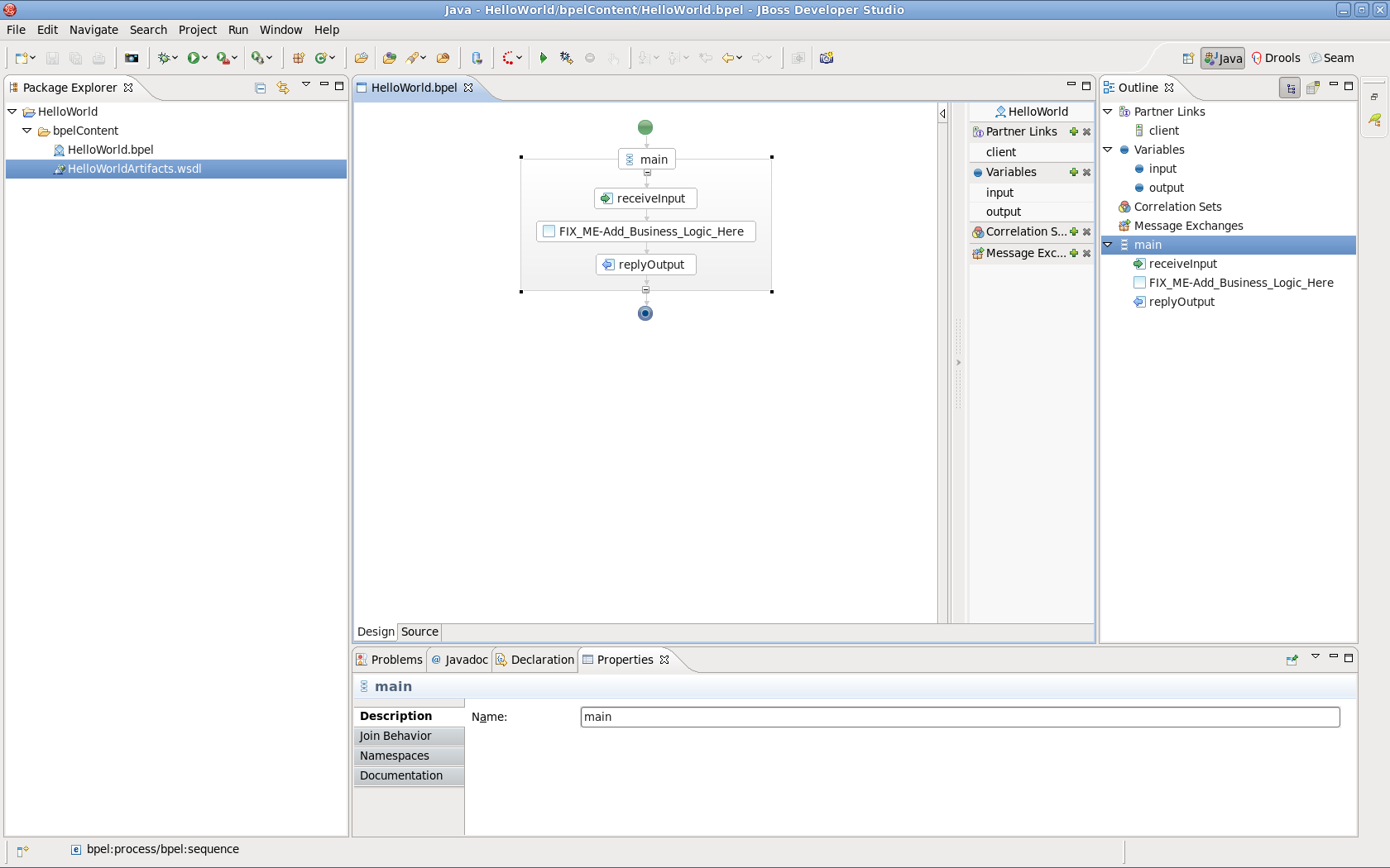
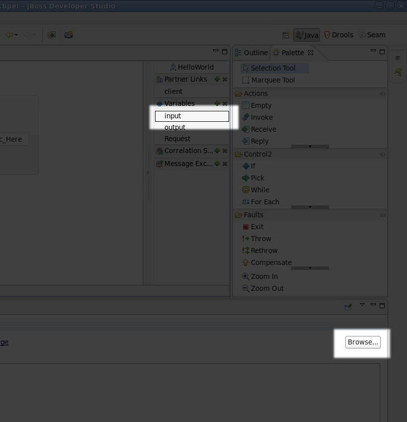
If the Properties view and Palette view are not opened, you can open the views by right-clicking the BPEL editor and selecting the Show in Properties or Show Palette in Palette view options. Then you should have the view like this:
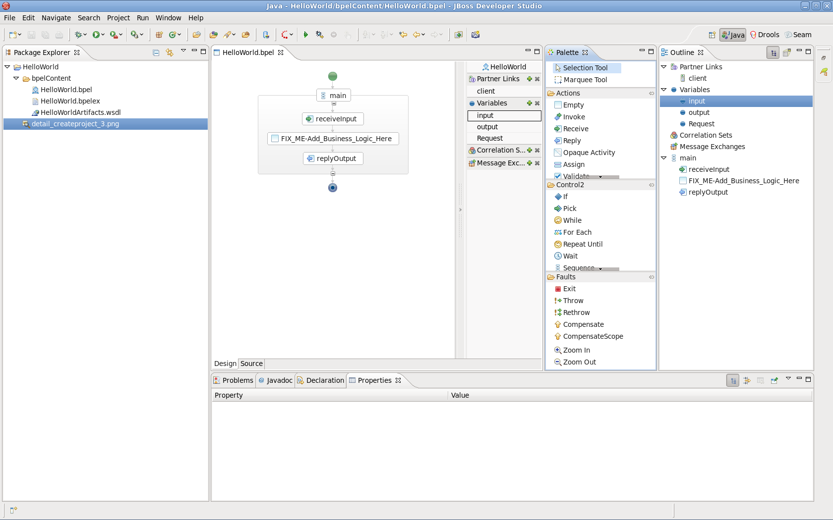
In the Palette view, you can drag a BPEL element to the BPEL editor and drop it in the place you want.
In the Properties view, you can view the information on every element in the BPEL process. The contents of the Properties view is automatically updated as elements are selected in the BPEL editor. The table below describes the tabs shown in the Properties view:
Table 2.3. Tabs of the Property view
| Tab | Description |
|---|---|
|
Description |
Shows the descriptive information about the element, e.g. Name of the element. |
|
Details |
Shows the detailed and important information about the element. It is the most important section of an element. Most of the properties of an element are set in this section. |
|
Join Behavior |
Shows the Join Failure property of the element. |
|
Documentation |
Shows the documentation sub-element of an element. |
|
Other |
Every BPEL element has its own sections: Correlation section, Message Exchange section, and so on. These sections will be covered in later sections. |
In order to see how a simple BPEL process works in action, you should do some steps as below:
Modify two variables of the process:
Add an Assign element between the receiveInput element and replyOutput element.
Click the Assign element in the BPEL editor in order to get the properties information of it in the Properties view.
Set its name in the Description tab as assignHelloMesg.
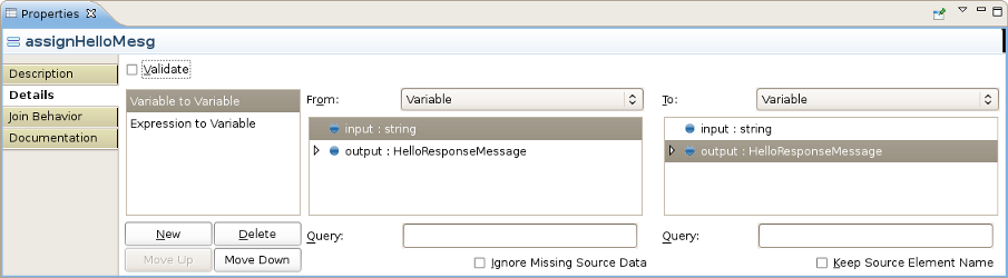
In the Details section of Properties view, you should click the New button to add a copy sub-element to the element. Assign "Variable to Variable"(input:string to output). At this time, an "initializer" popup dialog appears. Click on the Yes button in the dialog.
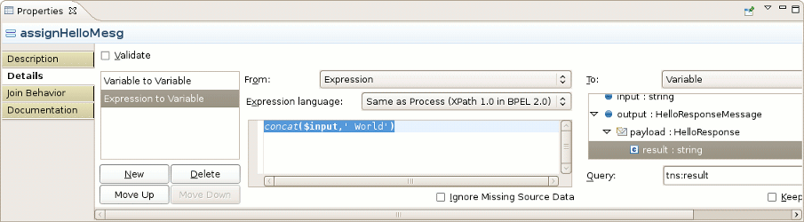
Then you should click the button once more and select Expression to Variable (assign
concat($input,' World')) to result:string.
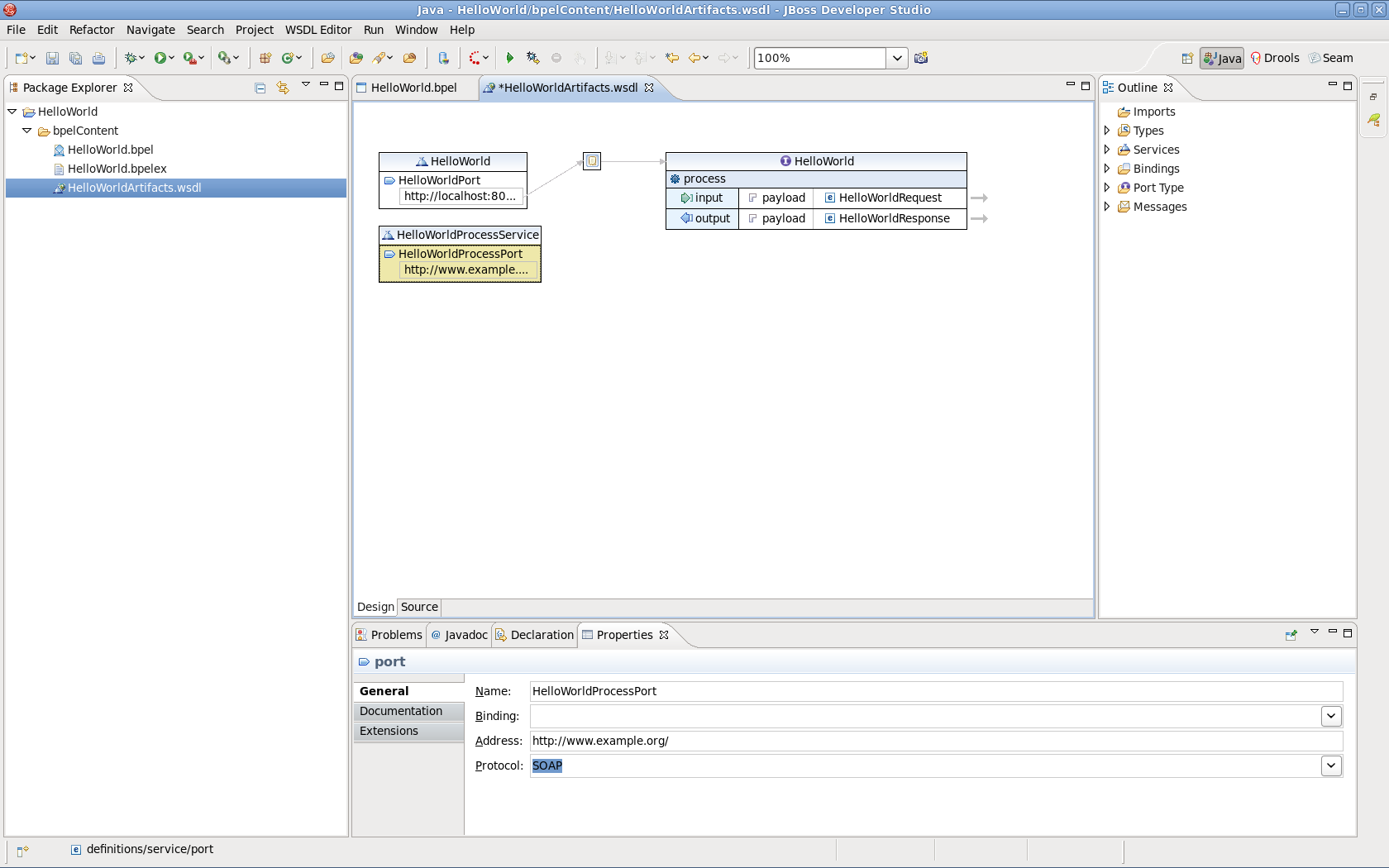
The HelloWorldArtifacts.wsdl file is added a service when you create a BPEL process file. A default service is already defined in this WSDL file. However, if you want to add your own service, follow the steps below:
Open the file
HelloWorldArtifacts.wsdlin the HelloWorld project by double-clicking the file. Right-click the WSDL editor and select the Add Service option. A new service should appear in the editor. Name it HelloWorldProcessService. It has the Port named NewPort. Select it, right-click on it and rename it to HelloWorldProcessPort in the Properties view.Right-click somewhere in the whitespace of the WSDL editor and select the Add Binding option. A new Binding component will appear in the editor. Name it HelloWorldSOAPBinding. Select it, and in the General tab of the Properties view and select HelloWorld as a port type in the PortType field. Then click on the button to open the Binding Wizard. In the wizard, select SOAP as the Protocol. Finally, click the button to close the wizard.
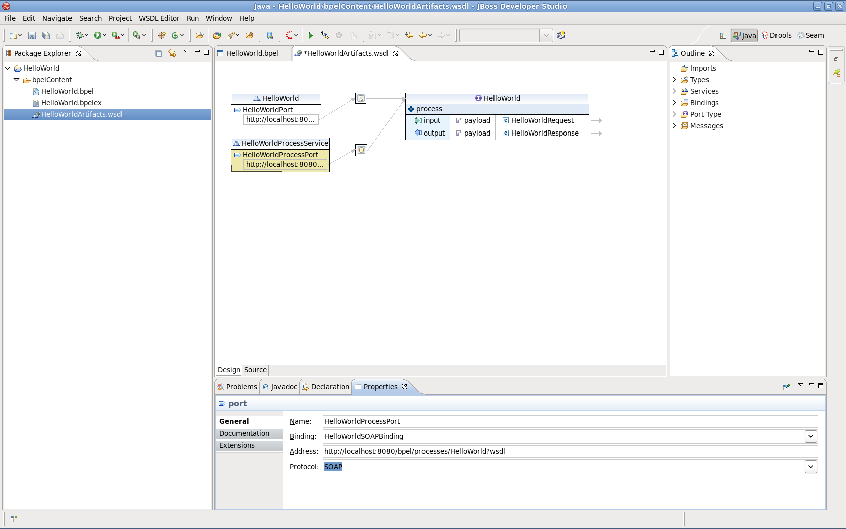
Click the HelloWorldProcessPort property in the General section of the Properties view, select HelloWorldSOAPBinding in the Binding combobox. Enter http://localhost:8080/bpel/processes/HelloWorld?wsdl in the Address field.
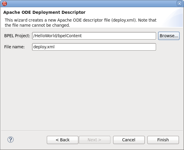
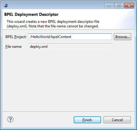
If you want to deploy a BPEL project to the JBoss BPEL Runtime, a deploy.xml file needs to be created. The steps below show you how to create this file:
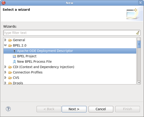
Create the
deploy.xmlfile by selecting → → → → . Click the button.On the next wizard page you should enter the following information:
BPEL Project : Click the button to select the BPEL project in your workspace where you want to deploy to the runtime. Please note that you should select the
bpelContentfolder in your new BPEL project for the BPEL Project field because this is the correct location for thedeploy.xmlfile.File name: The default value is
deploy.xml. This should not be changed.Click on the button to close the wizard and a new
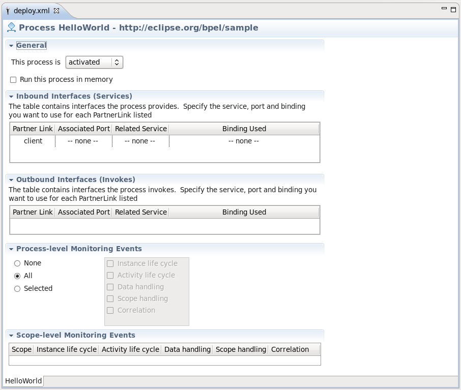
deploy.xmlfile will be created.Double-click the
deploy.xmlfile to open it in ODE Descriptor Deployment Editor. In the Inbound Interfaces section, click the Associated Port column and select HelloWorldProcessPort in the combobox.The Related Service and Binding Used columns should be automatically filled in. Save the changes to thedeploy.xmlfile.
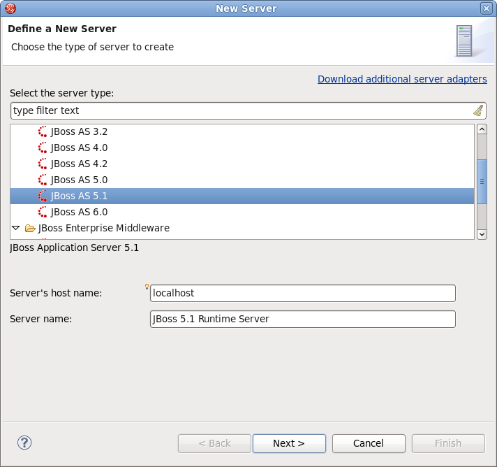
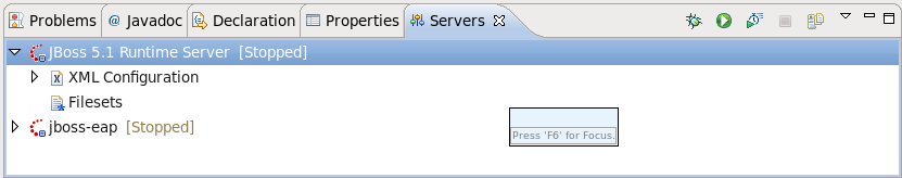
Once you have installed the JBoss BPEL Runtime-RiftSaw, you can create a server for JBoss BPEL runtime.
Open the Servers view by selecting → → → → .
Right-click the Servers view and select → to open the New Server wizard:
Select JBoss AS 5.1 as a server type.
Note
Please note, that only JBoss As 5.1 or higher version supports BPEL.
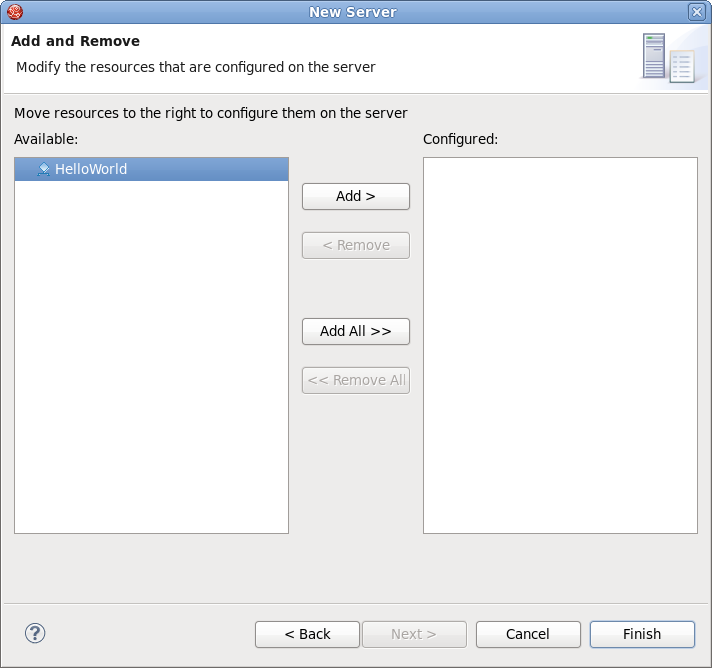
Click the button. On the next page, you should input your JBoss As™ location. Then click the button and you will get the page like this:
Select HelloWorld, then click the button to add the project to the server. Finally, click the button.
Start the server by right-clicking on the server and selecting the Start item.
Read the JBoss Server Manager Reference Guide for more detail on this process.
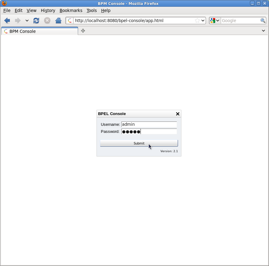
You can enter the link http://localhost:8080/bpel-console/app.html in your web browser to access the deployed processes.
Please visit the JBoss Tools Users Forum for more information and assistance.
Correlation sets are used to identify ongoing conversations between a client and the BPEL process. Typically, a correlation is an element in a message that uniquely identifies the conversation between client and service; for example, an Order ID or Social Security Number. This also identifies a specific process instance being managed by the BPEL engine.
In many cases a single element of a message is not enough to make it unique, so correlations can be defined as composites of several fields. Since a conversation can involve many different types of messages. Different correlations will need to be defined for each message type.
To create a correlation for a messaging activity (for example: Invoke, Receive, Reply), select the activity and then click on the Correlation Detail property tab. This will display the Select a Property dialog.
You canselect an existing property defined in the WSDL or click to create a new WSDL property, which will display the Create Message Property dialog.
Enter a name for the new WSDL property and its type. Either an XSD simple type or an XML Schema element.
Next, click the button to select a type. This will display the Type Selection dialog.
Click New in the Aliases section to create a new WSDL property alias.
Select either the Message Type, XSD Simple Type or XML scheme Element radio button and click to select its type. Then click .
Described are the user interface controls of BPEL Designer, and how they relate to the OASIS standard. If you are new to BPEL it is recommended that you first become familiar with the concepts surrounding the technology, detailed in ???.
The New BPEL Project wizard creates a faceted project which allows it to be deployed to the JBoss Riftsaw runtime engine. It is available by selecting → → → → .
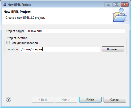
The wizard consists of a single page:
Enter the project name and select its location. When the wizard is completed the following files would have been created:
bpelContentfolderProject facet metadata
The bpelContent folder contains all the files necessary for your project. This includes all WSDL and XSD files.
The New BPEL Process File Wizard will create a BPEL process based on one of several templates defined by the wizard. The wizard assumes the new BPEL process is to be created in the curently selected project of the Project Explorer or Navigator view. If a BPEL process of the same name already exists within the project, a warning message will be displayed before any action is performed.
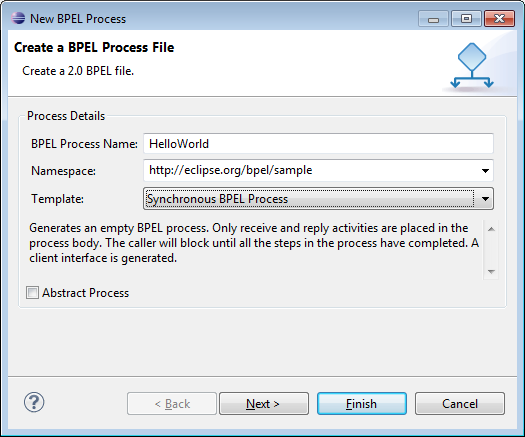
The first page includes the following options:
Table 3.1. New BPEL Process file wizard. First page options.
Field Description Default Name Enter the process name. no default value Namespace Enter the namespace URL. All namespaces should follow the W3C recommendation ( http://www.w3.org/1999/10/nsuri). no default value Template Select one of the provided templates: Asynchronous BPEL Process - generates the basis of orchestration logic: receive and reply activities are included into the process; client WSDL is generated, service is defined in the parentlink of the process. The caller is notified asynchronously when the process completes.
Empty BPEL Process - list of services participating in this BPEL process together with the one of messages used within the process is empty.There are no any orchestration logic.
Synchronous BPEL Process - similar to Asynchronous BPEL Process template except the fact that here the caller is notified synchronously when the process completes.
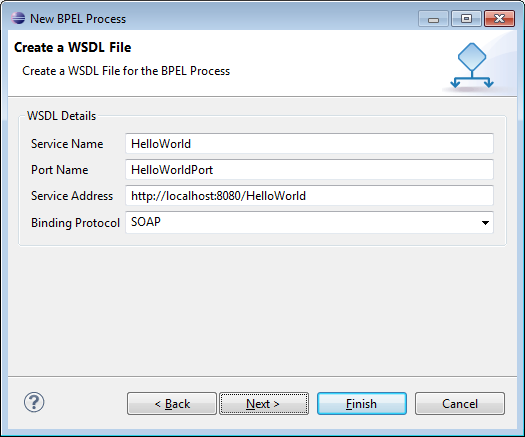
Asynchronous BPEL Process Abstract Process Specifies the created process as an abstract one -partially specified processes that are not intended to be executed. unchecked The second page of the wizard defines the process interface (WSDL file) including the web service address, port definition and protocol. The wizard will populate all of these fields with appropriate default values based on the information provided on the previous page.
The second page includes the following options:
Table 3.2. New BPEL process file wizard. Second page options.
Field Description Default Service Name Enter a WDSL service name for the BPEL process. The process name Port Name Enter a WDSL port name for the BPEL process. The process name + 'Port' Service Address Enter an address of the WDSL service for the BPEL process. http://localhost:8080/ + process name Binding Protocol Choose the binding protocol that you use in the WDSL: SOAP or HTTP SOAP The final page allows you to select the target project and folder for the new process artifacts. If a process with the name you provided already exists in that project and folder, the wizard will display an error message.
If the project is not a BPEL Project (does not define a BPEL facet) the wizard will display a warning message. You can still create the BPEL process, however it will not be deployable to a BPEL runtime engine until the BPEL facet has been added to the project (see the menu for more information about project facets).
Important
BPEL artifacts must be contained somewhere within the
bpelContentfolder hierarchy if you intend to deploy the process. Complex projects may be organized into a folder hierarchy, but these folders must be contained withinbpelContent.The
Deployment Descriptorfile must be contained within thebpelContentfolder and at the root of any folder hierarchy.You will be asked if you wish for the BPEL persepective to be opened once this wizard completes.
Use this wizard to create a Deployment Descriptor file. This file is a manifest for the web service and is required if the BPEL process is to be deployed to a runtime engine.
The page includes the following options:
Table 3.3. New BPEL Process file wizard. First page options.
Field Description BPEL Project Select the project and folder where the new Deployment Descriptorwill be created. This must also be the root folder that contains the BPEL processes.File name This field is automatically filled and cannot be edited. The BPEL Deployment Descriptor Editor will open once this wizard completes.
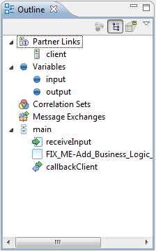
The Outline view provides a structural layout of the BPEL process. You can view the process as either a hierarchical tree-structured outline (![]() ) or as a thumbnail view (
) or as a thumbnail view (![]() ), by pressing the associated button.
), by pressing the associated button.
The primary editing, creation and viewing tools of the BPEL Designer are accessed from the Palette. The Palette can be docked either at the right or left edge of the BPEL Designer main window, or it can be detached and displayed in its own view.
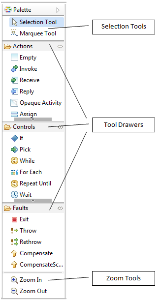
Selection Tools
The Selection Tool is used to select individual activities in the editors drawing canvas. Multiple activities can be selected by holding the CTRL or SHIFT keys in combination with left mouse click. The Marquee Tool allows selection of groups of activities by dragging a selection rectangle around them.
Tool Drawers
BPEL activities are created by dragging icons from the labeled Actions, Controls and Faults palette sections (or drawers), onto the editor’s drawing canvas. These sections can be collapsed and expanded by clicking on individual palette section titles. They can also be pinned to prevent them from collapsing if another section is expanded.
Zoom Tools
The tools at the bottom of the Palette are used to expand or shrink the drawing canvas.
This panel is embedded in the BPEL Designer canvas and provides a quick overview of the BPEL elements that are defined for the currently selected activity or BPEL process.
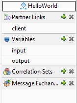
The process name appears at the top of the Dashboard. The main Dashboard area lists all of the Partner Links, Variables,Correlation Sets and Message Exchanges currently defined for the process. The green plus symbol and grey x symbol allow you to add and delete each of these elements. In-line editing of all element names works by selecting the name and then clicking again to enable the editor.
This section describes the Property Sheet tabs that are common to many activities.
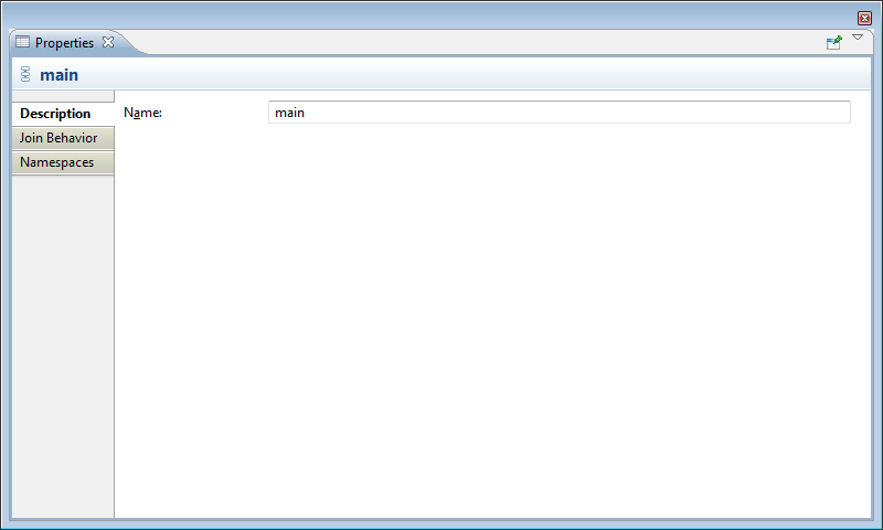
The Description tab contains the activity name. Names must follow XML element naming conventions, limiting characters to letters, numbers and certain special characters only (spaces are not permited). For further information on XML element naming conventions, see http://www.w3.org/TR/xml/
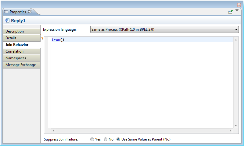
Join conditions are evaluated by the target activities of links. With the drop-down Expression language menu, enter an XPath expression that defines the condition of the join. The Suppress Join Failure behavior defined by the process or a containing scope can be overridden with the radio buttons at the bottom.
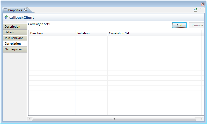
The Correlation tab lists all correlations that are used by the currently selected Receive, Reply or Invoke activity. Correlations can be added to or removed from the activity through this tab.
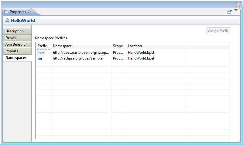
Namespaces are URIs (Uniform Resource Identifiers) that uniquely identify a set of resources on the Internet. Because URIs can be very lengthy, shorthand aliases called prefixes are typically defined and used in XML files to make the XML more readable.
The Namespaces tab lists all of the namespace URIs and their prefixes in scope for the currently selected activity. Whenever you create a reference to an external property (an element defined in an XSD) whose namespace has not yet been assigned a prefix, the BPEL Designer will prompt you to create a prefix. This can also be done beforehand through the Namespace tab of the Properties sheet for the property by clicking the button.
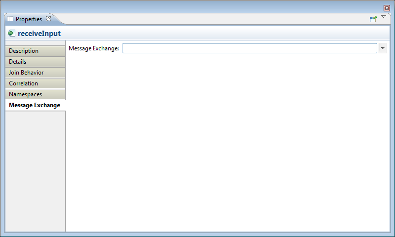
Message exchanges are used to associate a Reply activity with an inbound message activity and can be either a Receive, OnMessage or OnEvent. These are descriptive names given to a request-response conversation between two parties and must conform to XML element naming conventions. For further informaiton on XML element naming conventions, see http://www.w3.org/TR/xml/.
This section describes the Property Sheet tabs that are unique to process activities.
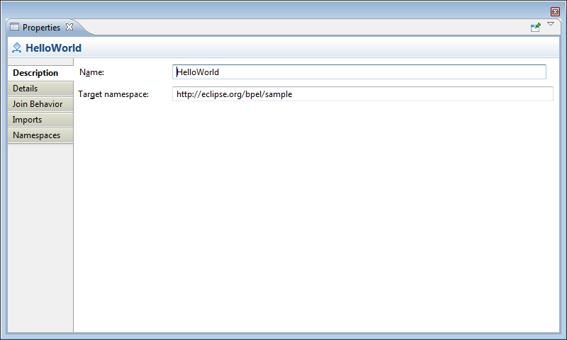
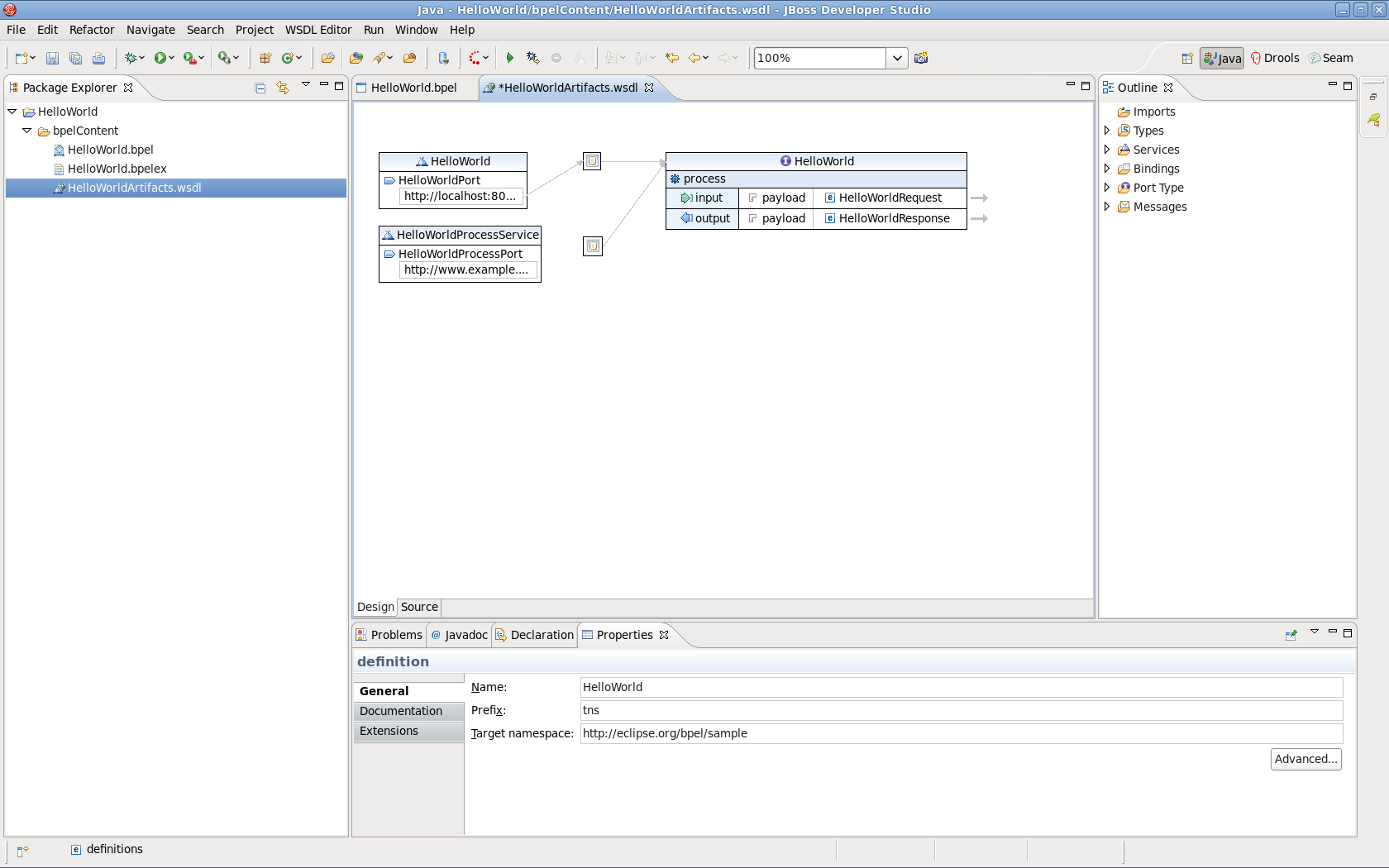
The Description tab allows you to change the process name and its namespace URI. All namespaces should follow the W3C recommendation (http://www.w3.org/2005/07/13-nsuri.
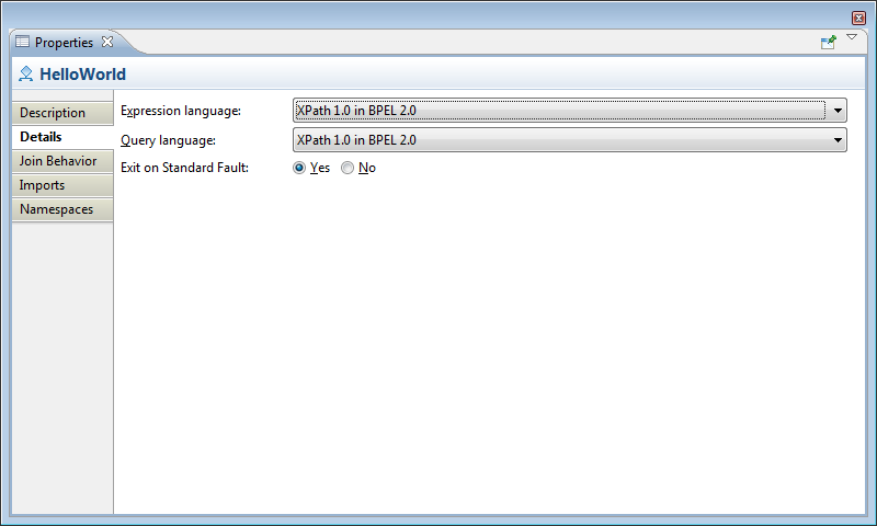
The Process Details tab allows you to select the default Expression and Query language. If you set Exit on Standard Fault to Yes, it will cause the process to terminate if a WS-BPEL standard fault, other than a join failure, is encountered.
Note
Currently only XPath 1.0 is supported.
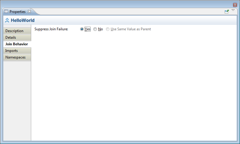
The Process Join Behavior tab determines how the process will handle join failures. When set to Yes, any JoinFailure fault (detailed in the WS-BPEL Standard Faults section of the OASIS specification: http://docs.oasis-open.org/wsbpel/2.0/OS/wsbpel-v2.0-OS.html#_Toc164738543) will be ignored for all activities in the process. An activity is able override this value, or inherit the value from its parent.
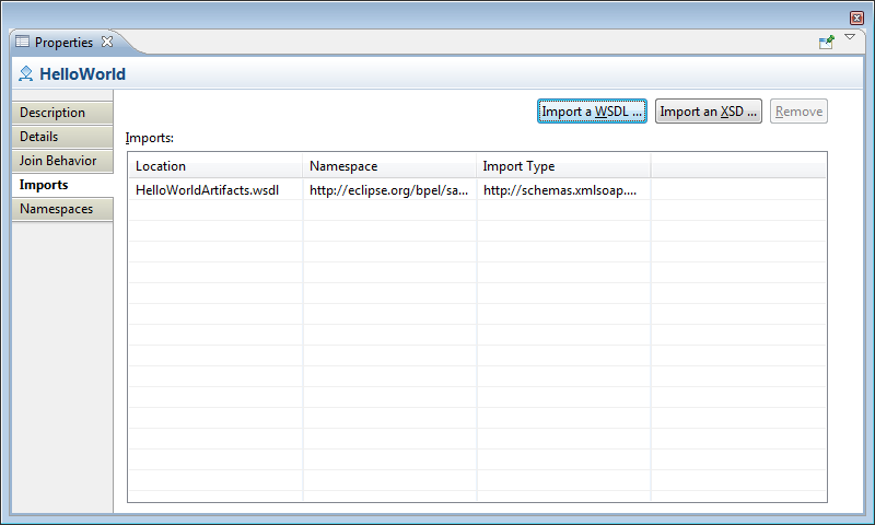
The Imports Detail tab lists all of the imported service interfaces (WSDL) and XML Schemas (XSD) used by the process. Additional WSDL and XSD files can be added to the imports on this page. After a new resource has been imported, you may assign a prefix to the namespace URI from the Namespaces tab.
Note
Imported resources must be located in the project root folder (bpelContent by default) or in a sub-folder.
For information on the Namespaces tab, see Section 3.3.4.1.4, “Namespaces tab”
This section describes the Details tab and its attributes as they will appear for individual activities. Several activities share common detail elements, but all are presented here for your reference.
Partner Links help define the conversations between two services. They define the roles each partner plays in the conversation and the types of messages that can be exchanged between them.
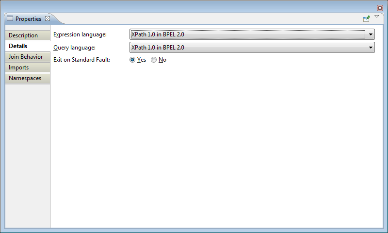
The Details tab allows you to choose the Expression language and Query language for selecting elements of a Partner Link.
Note
Currently only XPath 1.0 is supported.
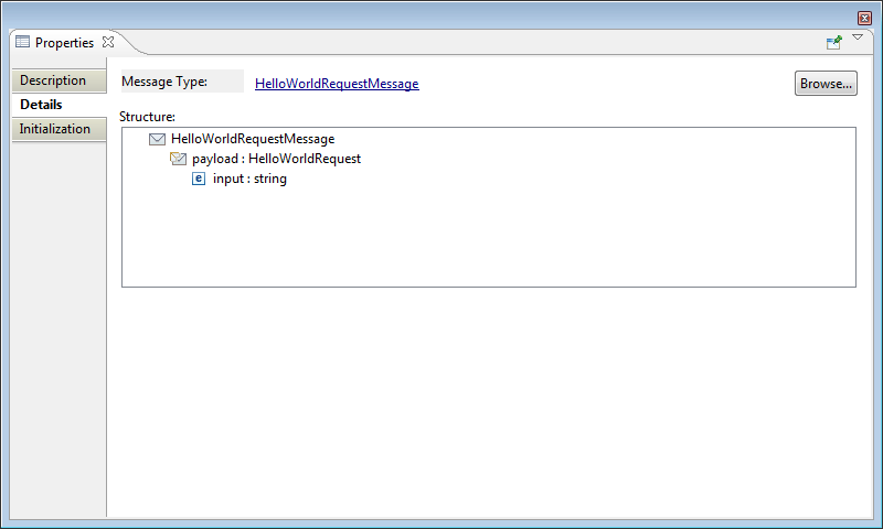
Variables are used in BPEL to store inbound and outbound messages for examination and manipulation by the business logic; they can also be used to save intermediate results and the process state. There are three kinds of variable declarations: messages types, XML Schema types and XML Schema elements.
The Details tab allows you to define the variable declared type and its structure by selecting from known types. Once a variable type has been defined, the structure of the variable is shown. Clicking on the hyperlink will open the WSDL or XML Schema editor for the selected type or element.
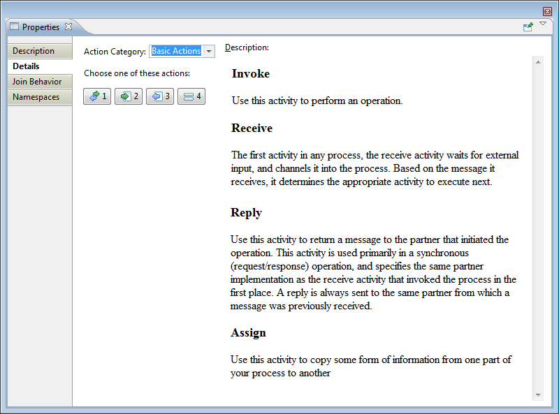
The Empty activity is a placeholder for any undefined Basic Activity and is intended to eventually be replaced by a real activity before the process can actually be executed. If the BPEL engine encounters an Empty activity, it is ignored.
The Details tab allows you to select one of four basic actions: Invoke, Receive, Reply and Assign. Hovering the mouse over one of the selection buttons displays a brief description of that activity.
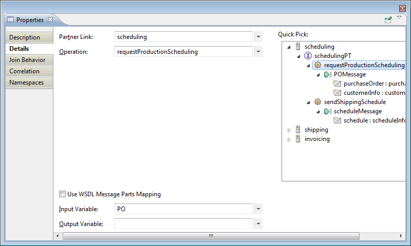
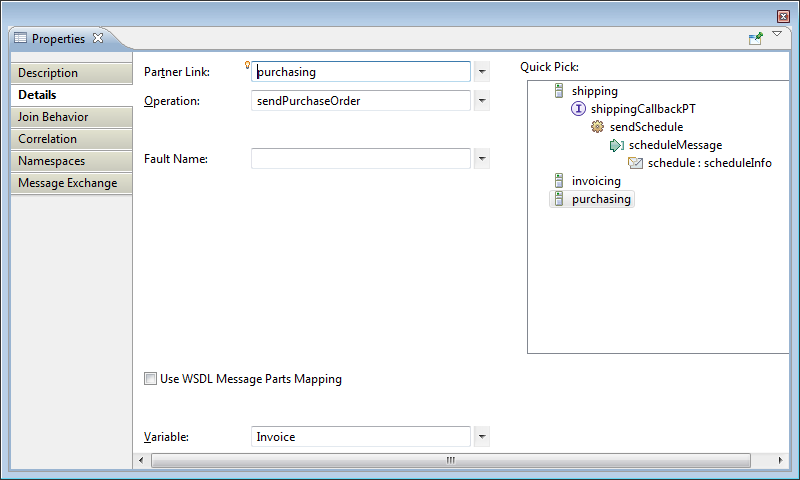
The Invoke activity requires a Partner Link name and an Operation as defined in the WSDL for that service. You can use the Quick Pick tree control at the right to select the Partner Link and Operation. For one-way invocations of the service, specify only an Input Variable; for request-response invocations you must also specify an Output Variable.
The checkbox labeled Use WSDL Message Parts Mapping provides an alternative to using variables for the request message.
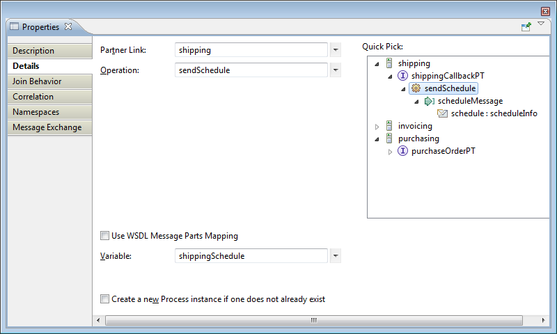
A Receive activity requires a Partner Link name and an Operation as defined in the WSDL for this service. You can use the Quick Pick tree control at the right to select the Partner Link and Operation. A previously defined variable can be used to hold the message data, or the Use WSDL Message Parts Mapping checkbox can be set to store the incoming message in an anonymous WSDL message variable.
The Create a new Process Instance checkbox, when enabled, will cause the BPEL engine to start a new process. This will start a new conversation with a client.
A Reply activity requires a Partner Link name and an Operation as defined in the WSDL for this service. You can use the Quick Pick tree control at the right to select the Partner Link and Operation. A previously defined variable can be used to provide the response message data, or the Use WSDL Message Parts Mapping checkbox can be set to use the data from the anonymous WSDL message variable.
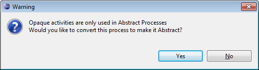
Opaque activities are only used in abstract processes, and are meant as placeholders for other activities or complex business logic that has not yet been determined. When you drag and drop an Opaque activity onto the drawing canvas, the process will be converted to a non-executable, abstract process. The BPEL Designer will inform you about this by displaying a warning dialog.
The Assign section is probably one of the more complex pages in the BPEL Designer, due to the nature of the BPEL Assign activity. The figure below shows the detail tab of an empty Assign activity with callouts describing each component:
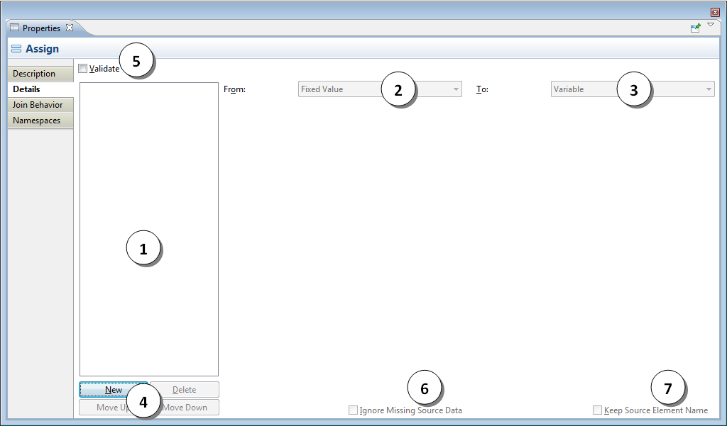
List (initially empty) of assignment operations currently defined.
From combo box for selecting the source element category.
To combo box for selecting the target element category.
Contents and order management buttons. The button adds a new assignment operation to the list. When clicked, the From and To combo boxes become active and display Variable. These allow you to select the source and categories for target items.
Validate checkbox; when enabled will cause the BPEL engine to validate the data after the assignment. If an error is detected it will cause a fault, which can be caught by a fault handler in the BPEL process.
Ignore Missing Source Data checkbox; When enabled, missing source data is not considered an error (no fault will be generated).
Keep Source Element Name checkbox; when enabled, the complex target variable element names will not be replaced by the source element names if they differ.
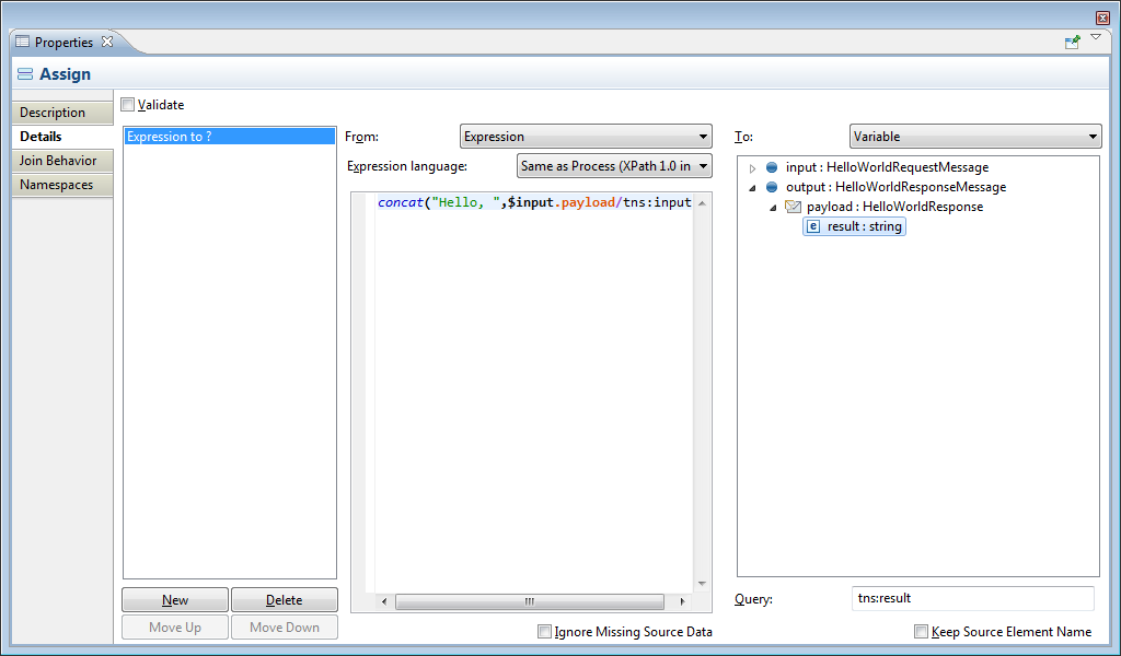
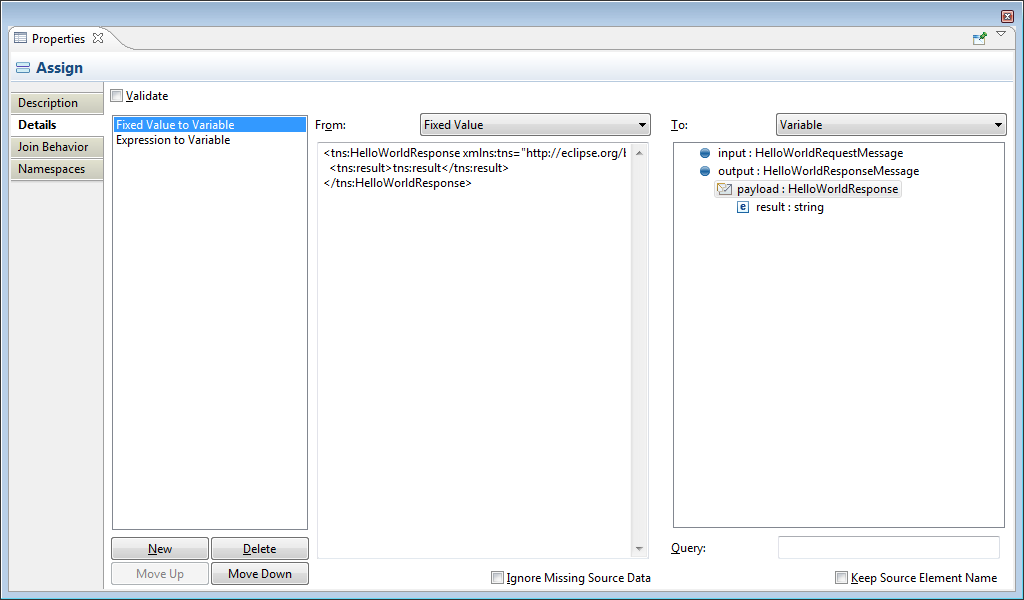
The following figure shows the detail tab of an Assign activity which has an XPath expression as the source (From) and a process variable element as the target (To):
A requirement of the BPEL language is that all complex variables must be initialized with valid XML before they are referenced either as a target of an assignment, or in another BPEL activity. The BPEL Designer understands this and, once you have selected the target of an assignment operation, it will ask if you would like to have an XML fragment generated for the target variable:
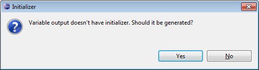
Unless you are certain that the variable has been initialized during a previous assignment operation or other activity, you should click . The figure below shows the Assign details tab after the initializer has been generated:
Assignment Operation Categories
Additional type selection or data entry widgets will appear below the From and To combo boxes, depending on the source and target item categories selected in the combo boxes. Initially these will be controls for the selection of process variables, since the default combo box selection is Variable. The possible source and target categories are described in the following table:
Table 3.4. Possible source and target categories
| Category | Control type | Can be source? | Can be target? | Further information |
|---|---|---|---|---|
| Variable | Tree | Yes | Yes | Select an in-scope variable or any portion if it is a complex variable. The target of the assignment must have the same type (for simple variables) or structure (for complex variables) as the source. |
| Expression | XPath | Yes | Yes | Enter a valid XPath expression with the XPath editor. For targets, the expression must resolve to an L-Value; that is, it must be a variable reference. |
| Fixed Value | Text | Yes | No | Enter a valid XML fragment that is compatible in structure and data type with the target. |
| Property of a Variable | List | Yes | Yes | N/A |
| Partner Link reference | List | Yes | Yes | N/A |
| Endpoint reference | List | Yes | No | N/A |
| Opaque | None | Yes | No | N/A |
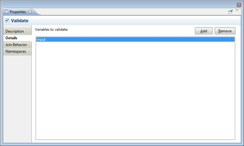
The Validate details tab contains a list of variables to be validated.
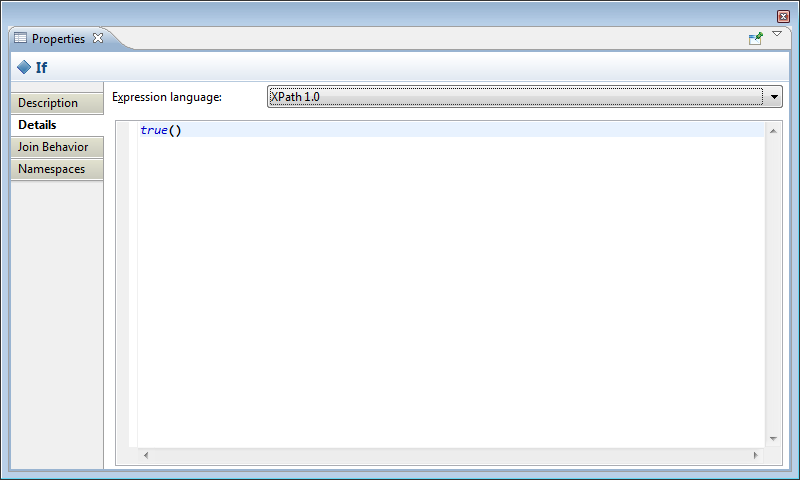
These activities have the same details tab, which allows you to specify an XPath expression to be evaluated for the conditional activity.
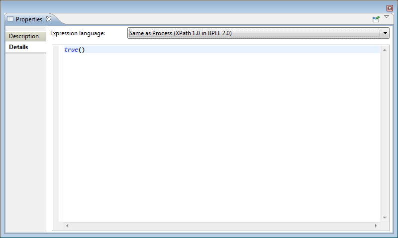
The Link detail tab allows you to specify a condition that will cause Flow synchronization to be satisfied and allow the target activity to continue. This is similar to the details tab of the other conditional activities.
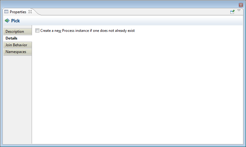
The Pick details tab allows you to specify whether the event will create a new process instance.
The OnMessage activity is used in either a Pick or event handler.
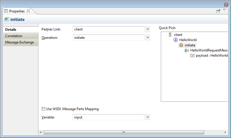
The Details tab allows you to specify the Partner Link, Operation and Message Type expected by the activity, and the process variable that will contain the received message data.
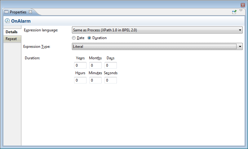
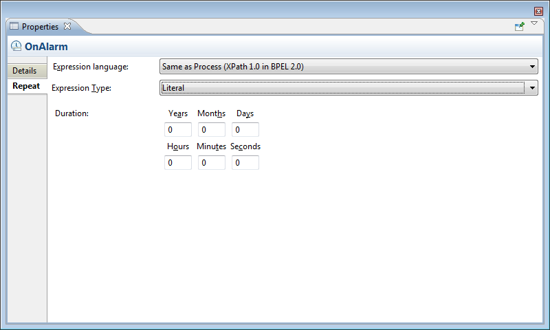
The OnAlarm activity is used in either a Pick or event handler to handle timeouts while waiting for messages to arrive. This activity can be configured to wait for a certain period of time or until a specific date and time.
The Details tab allows you to specify the Partner Link, Operation and Message Type expected by the activity, and the process variable that will contain the received message data.
Repeat conditions are only allowed for an OnAlarm in an event handler. This allows the activities enclosed in the activity to be executed repeatedly. Repeat duration is the amount of time the process will wait before each repetition. The Repeat screen follows:
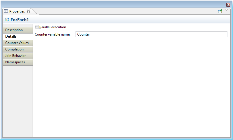
The details tab of the ForEach activity allows you to specify a counter variable to be used for keeping track of the loop iterations. The Parallel execution checkbox, when enabled, will execute all iterations in parallel.
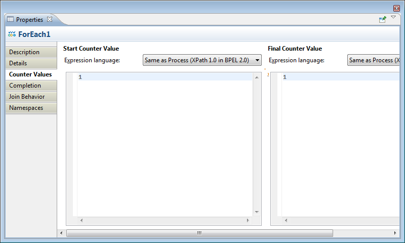
The Counter Values tab is where the required starting and ending counter values are specified.
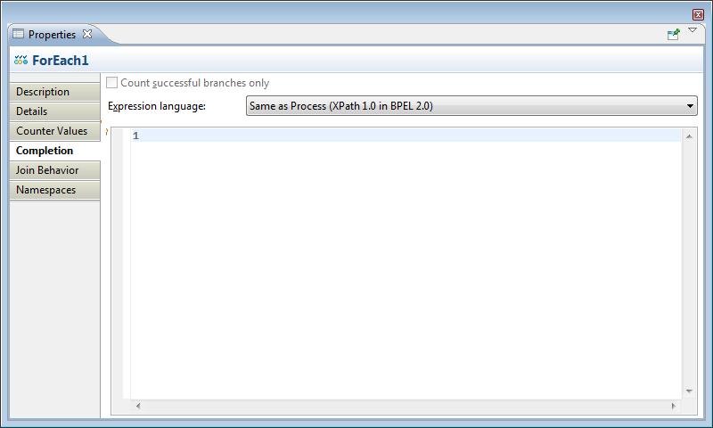
The optional Completion tab allows you to specify the early termination condition for the loop.
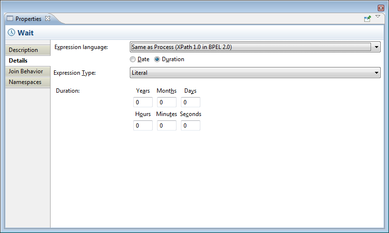
The details tab of the Wait activity allows you set a delay (Duration) or specify a date and time (Date) for when to continue process execution.
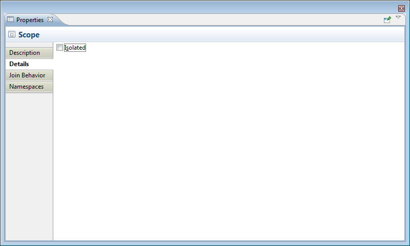
The details tab for the Scope activity allows you to define whether the Scope is isolated.
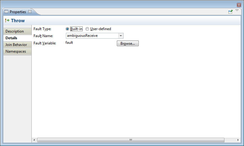
The Throw activity will invoke a fault handler in an enclosing Scope activity. Throw requires the name of either a standard BPEL fault, or the name of a user-defined fault message. A variable is used to hold the value of the fault data.
This section discusses the features of the BPEL Designer. See Section 3.3, “Views” for a detailed discussion of each of these features.
Drawing Canvas: This contains the graphical representation of the BPEL process and is displayed when the Design tab at the bottom of the editor window is selected. The primary mouse click action (default is left mouse button) on any of the activity names activates an in-line editor, allowing you to edit the process name. To finish editing, simply press the ENTER key or change focus by clicking on a different window control.
The Source tab displays the XML (text) representation of the process. Any changes made in one view are immediately reflected in the other. The default layout of activities is top-to-bottom, but can be changed to horizontal layout from the context menu.
Palette: The primary editing, creation and viewing tools of the BPEL Designer are accessed from the tool Palette.
Dashboard: Provides an overview of the BPEL process.
Property Sheet: When an activity is selected in the drawing canvas, its properties are displayed in the tabbed Properties sheet.
Outline: This panel provides a structural view of the BPEL process.
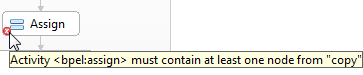
The BPEL Designer will validate your business process every time it is saved. If an activity is found to be incomplete or incorrectly configured, it will be decorated with an error icon (red circle with an X) as for example the Assign activity below:

Hovering your mouse over this icon will display an error message in a tooltip:
The remainder of this section discusses some basic BPEL concepts and how they relate to the BPEL Designer.
Basic activities are represented on the drawing canvas as rounded rectangles containing an icon and the user-defined name of the activity. The Actions section of the Palette contains all of the basic activities. For example: Assign, Invoke and Receive.
Most basic activities will require some additional configuration. See Section 3.3.4, “Property sections” for more information.
Every BPEL process has implicit Start  and End
  activities. These do not correspond to actual BPEL elements however, and are simply placeholders for visualizing the beginning and end of the process flow.

The Assign activity allows you to manipulate variables and message contents that are defined in the process. See Section 3.3.4.3.8, “Assign” for more information.

The Invoke activity is used to send a message to an external service (one-way invocation), and optionally wait for a response (request and response). An Invoke can also define a compensation handler and a fault handler to handle exception conditions. See Section 3.3.4.3.4, “Invoke” for more information.
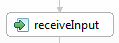
The Receive activity will wait for a specific message type from a service client. See Section 3.3.4.3.5, “Receive” for more information.
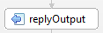
The Reply activity is used to respond to clients with a specific message type, or fault message (if defined for the process interface). See Section 3.3.4.3.6, “Reply” for more information.
The Validate activity is used to validate the values of variables against their XML Schema and WSDL data definitions. This includes the variable’s data type as well as structure. If validation fails, the BPEL standard fault invalidVariables is thrown.
Validation is typically performed just before sending messages to a partner or client, or after receiving a message to ensure the message contains all required data and that the data is as expected. See Section 3.3.4.3.9, “Validate” for more information.

A Wait activity will delay process execution for a certain amount of time, or until a given date and time; this is typically used to invoke an operation at a certain time. For example to update process state hourly or daily, or to collect some information from another service at a certain time of day. See Section 3.3.4.3.16, “Wait” for more information.
Structured activities can be thought of as containers that can hold one or more activities. The Controls section of the Palette contains all of the structured activities. When you drag and drop one of these onto the drawing canvas, the BPEL Designer will create a basic skeleton of the activity, and assign default properties.
All structured activities will require some additional configuration before they are considered valid. For example, BPEL does not allow an empty Sequence activity. Invalid structured activities will be decorated with an error icon similar to basic activities.
Structured activities can be expanded and collapsed on the drawing canvas by clicking the plus and minus buttons at the bottom of the figure. Illustrated below is a collapsed and expanded Sequence:

The following sections describe the structured activities and how each must be configured to be considered vaid for BPEL.
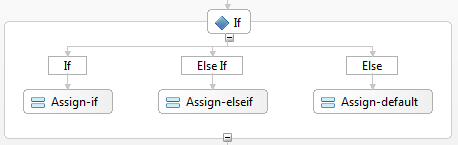
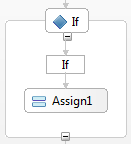
The If activity allows conditional execution of one or more sequences of activities. It consists of a sequence of one or more conditional branches defined by If and optional ElseIf elements. The elements are evaluated in left-to-right order (or top-to-bottom if you have selected horizontal layout). An optional Else branch will be executed if none of the other conditions are true.
An If activity must define a condition (expressed as an XPath) and an activity which is executed if the condition evaluates true. To insert additional ElseIf and Else elements, right-click the If figure and select the desired element from the context menu. The figure above shows a complete If activity with optional ElseIf and Else elements.
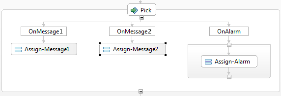
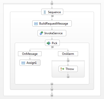
The Pick activity will cause the process to wait for one of any number of messages to be received. An optional timer can be set to limit the time to wait for receipt of these messages. Activities to handle receipt of messages and timer expiration are defined in the Pick. Message receipts are handled by OnMessage activities (Section 3.3.4.3.13, “OnMessage”), and timer expiration is handled by the OnAlaram activity (Section 3.3.4.3.14, “OnAlarm”).
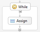
The While activity repeatedly executes the contained activity as long as a condition evaluates true at the beginning of each iteration. A While activity must define a condition and must contain an activity.
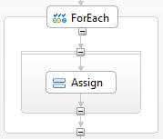
ForEach is a looping activity that executes the activities contained in its Scope a specified number of times. A counter variable, defined in the ForEach property detail tab, is used to keep track of the iterations. The ForEach properties must be configured with starting and ending value expressions for this counter variable. The counter is initially set to the starting value and activities in the Scope are executed until the counter exceeds the ending value.
This activity can also be configured to execute all iterations in parallel, meaning the enclosed Scope activity behaves as if multiple Scopes are enclosed in a Flow activity.
An optional early termination value can be defined, which will cause the loop to complete before the counter has reached its ending value. The ForEach will complete when the counter is equal to this early termination value for the sequential execution case. For the parallel execution case, the early termination value is the number of completed iterations. For example, the ForEach completes when at least some number of some action have finished.
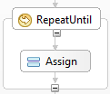
The RepeatUntil activity repeatedly executes the contained activity as long as a condition evaluates true at the end of each iteration. A condition must be defined for a RepeatUntil, and it must contain an activity.
A Sequence is a container for one or more other activities, which are executed in sequential order and (unlike Scope and Flow activities), has no other special characteristics. Because the conditional activities (If, While, RepeatUntil and ForEach) can have only one activity as the target of their execution, a Sequence is typically used to execute multiple activities.
For example, the If shown below contains only a single Assign activity:
If it were necessary to perform an assignment and then invoke another web service, the Assign and Invoke could be contained within a Sequence. The Sequence would then become the target of the If:
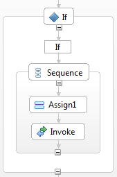
Note
The BPEL Designer will automatically create a Sequence if you drag-drop a second activity into any of the conditional activities.
A Scope provides a context for its enclosed activity. This context includes variables, partner links, message exchanges, correlation sets, event handlers, fault handlers, a compensation handler and a termination handler. These Scope contexts can be nested hierarchically where the root context is provided by the process itself.
A Scope can be thought of as a compartmentalized sub-process. If the Scope is declared as being isolated, then the variables and partner links shared with the process are locked to prevent other concurrent Scopes from altering them while a Scope is executing. Scope may also be nested to any depth and all variables, partner links and others defined in a Scope, are inherited by its children. Refer to Section 3.4.1.2.8, “Flow” for a discussion of concurrent execution.
To be valid, a Scope must have a single activity. The typical use of a Scope activity is to invoke a service and wait for a response message or timeout. In the above figure, the Scope has defined a message variable and a partner link used to interact with the invoked service.
The Flow activity allows multiple activities to be executed in parallel. All activities or Sequences of activities that are contained in a Flow, are executed (or begun) at the same time by the BPEL engine. A Flow completes when all of its enclosed activities have completed.
Parallel processing is typically used to save time by doing more than one thing at a time and as a result, speed up the process. However, in many situations several tasks can be started at the same time, but one or more tasks may depend on the successful completion of other tasks. This task dependency sequencing is called synchronization and is achieved using Links.
For example, a process that handles purchase orders for material goods needs to:
Calculate the total order price
Calculate shipping costs for the order
Send a customer invoice
All of these activities can be started at the same time, however the shipping cost must be finalized before the total order price can be determined, and the invoice can be sent.
To create a Link, right-click on the activity that must be completed first (the activity that is the source of the dependency) and select from the context menu. Next, move the mouse to the activity in the Flow that depends on this one (the target) and click the left mouse button to create the link.
A Link is identified by a name that must be unique within the Flow. The BPEL Designer generates a reasonable default name, but you can change this in its properties. You can also add a test to the Link that defines the conditions for considering an activity to be complete. For example an activity in a Flow may require two pieces of information, provided by other services, in order to continue. Consider the process Flow shown below:
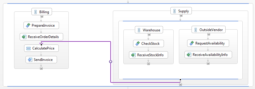
In this example, the Billing department can begin preparation of a customer invoice, but it needs to know if sufficient stock is on hand to fulfill the order and if an outside vendor needs to provide the additional quantities ordered. The following condition would enable the Link so that execution can continue for the price calculation and customer invoicing:
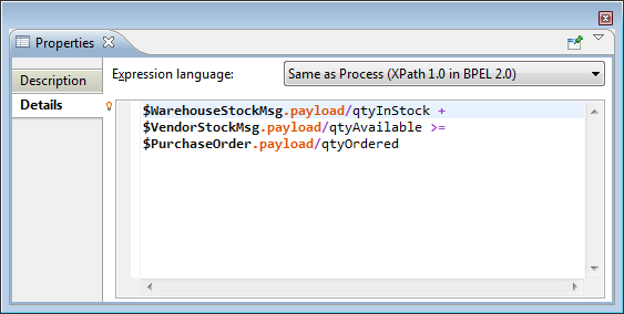
This process is only partially complete though as it does not consider the number of outside vendors, or if the total quantity being ordered can ever be filled.
Fault activities cause the normal process execution flow to jump to a specialized handler, similar to exceptions in modern programming languages. There are five different types of fault activities, described in this section.


The Throw activity propagates a specified fault to its ancestor Scope, or the process itself.

A Rethrow activity can only be used inside a fault handler. It is used to propagate the fault that was caught by the handler, using the original fault data.

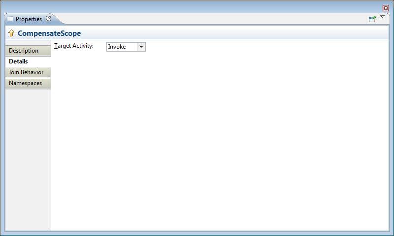
The Compensate activity is used to invoke a compensation handler. This activity can only be used within a fault handler, compensation handler or termination handler.

Handlers allow a BPEL process to recover from exception conditions. Exception conditions include: a timeout waiting for a response from a partner service, invalid or missing message data, a fault condition returned by a service. There are four types of handlers:
Fault handler
 : Executed when a fauly is thrown by an activity.
Compensation handler
 : Executed when the BPEL process encounters a Compensate or CompensateScope activity.
Temination handler
 : Executed if a Scope is forced to terminate early.
Event handler
 : Executed for events include the receipt of a message and a timer expiration.
Handlers are defined for the process or for certain activities. To create a new handler right-click an activity and select the desired handler from its context menu. The BPEL Designer will generate a skeleton of the handler within a collapsible window that is attached to the activity. The figure below illustrates all of the different types of handlers in their fully expanded view. The handler windows can be collapsed and expanded by clicking on their respective icon.
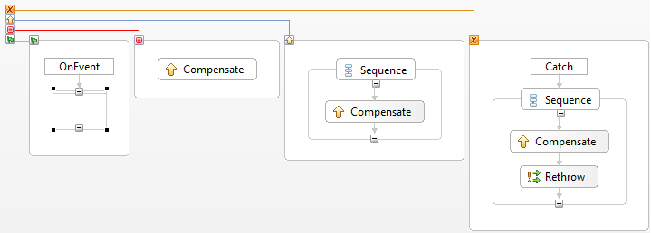
The behavior of handlers and the order of exception processing is complex and beyond the scope of this document. Refer to the OASIS WS-BPEL 2.0 specification at http://docs.oasis-open.org/wsbpel/2.0/wsbpel-v2.0.html for more information.
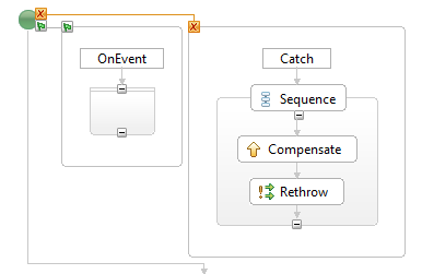
Fault and event handlers can be defined for the process by right-clicking the Start activity and selecting the desired handler from the context menu.
A Scope may have any handler. Since Scopes can be nested, each level can define its own set of handlers. Events that are not caught and processed by a handler in an inner Scope, will be propagated to its ancestors.
Before a BPEL project can be deployed to the runtime engine, you must create what is called a deployment descriptor. This is simply a manifest file, serialized as XML, that describes all of the BPEL processes and their interfaces to the BPEL engine. The deployment descriptor file must be created in the root folder of your project. See Section 3.1.3, “New BPEL Deployment Descriptor” more information.
The deployment descriptor editor traverses the folder hierarchy in your project and searches for all BPEL files. Each process is then represented in a separate tab in the editor. The figure below shows two processes (HelloWorld and GoodbyeWorld). Each process must be configured before the project can be deployed.
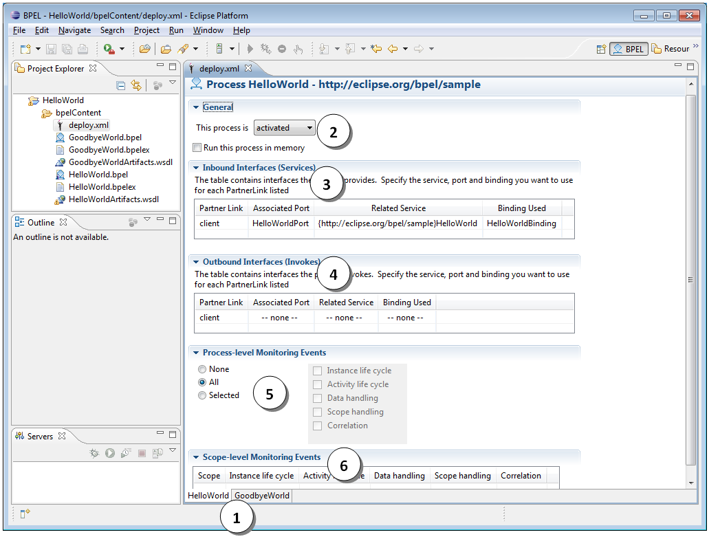
Process selection tabs: Click on these tabs to display the configuration page for each process.
Initial process state: The process can be deployed in either an active, inactive or retired state.
Inbound interfaces selection: Select the WSDL port type that clients will use to invoke this service.
Output interfaces selection: Each invoked service (if any) will require you to select its port type.
Process-level monitoring events: Allow you to select which events are generated by the BPEL engine. This is currently unused but will be used in future for debugging the process.
Scope-level monitoring events: The BPEL engine can be configured to generate monitoring events for each Scope defined in the process.
The only action required to configure a processes is to select the interfaces for inbound and outbound services used by the process; all other settings are optional.
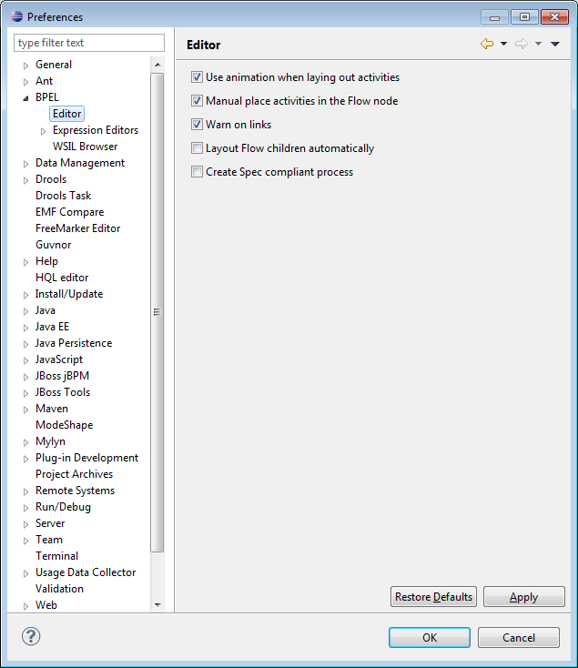
Certain aspects of the BPEL Designers behavior can be customized to suit your personal preference.
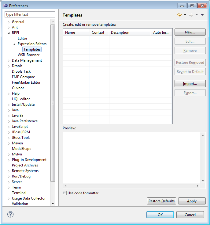
This preference page is used to configure the XPath expression editor templates and is similar to other Eclipse editor template preference pages.
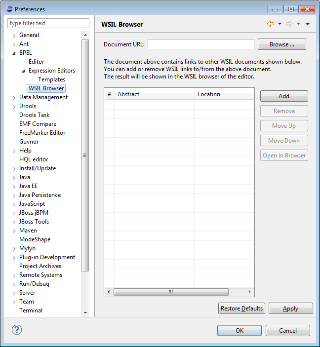
This preference page is used to configure a Web Services Inspection Language (WSIL) file. The file can contain references to WSDL files for external services as well as references to other WSIL files, either locally or on the web. This file is used to search for WSDLs when defining partner links in a process.
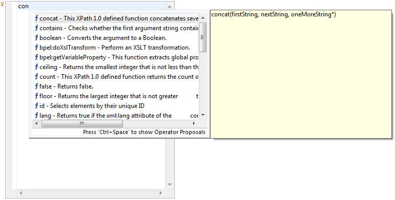
The XPath expression editor provides context-sensitive assistance in the form of pop-up proposals. The light bulb icon  indicates that content assist is available by pressing the CTRL and SPACE keys simultaneously. The editor will display appropriate help information based on what it knows about variables currently in-scope for the selected activity. An example is seen in the figure below:
Note
The BPEL 2.0 specification provides for the definition of an XPath language version at the process level, as well as the activity level (for those activities that make use of XPath). However, only XPath 1.0 is supported by the BPEL Designer and the JBoss Riftsaw runtime engine at this time.
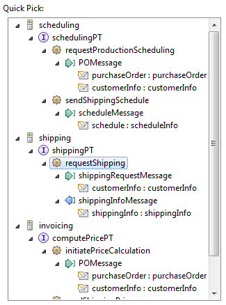
Tree control is used in many proeprty pages for selecting message parts, partner links and operations.
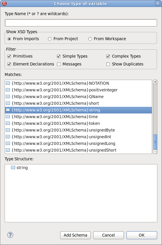
This dialog is displayed whenever the BPEL Designer requires you to select a message, message part, XML Schema type or XML element. Refer to the figure below for an explanation of each of the components of this dialog:
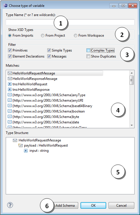
Type Name: Used to limit the items displayed in the Matches (4) list. Only items that begin with the text in this filter will be displayed.
Show XSD Types: Can be used to limit where the editor will search for XSD files.
Filter: Further reduces the number of matches according to types.
Matches: Displays the items matching the selected filters. Selecting an item in this list will update the Type Structure (5) tree view.
Type Structure: Displays the structure of the item selected in the Matches (4) list. Depending on the type of item requested, you may need to select an item from this tree control as well; the button being enabled is an indicated of a selection being required here.
: If the required XML Schema has not been resolved, you can add it to the process’ imports by clicking this button.
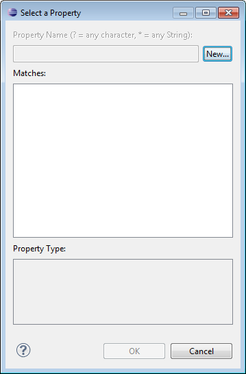
This dialog allows you to select an existing WSDL property or create a new one.
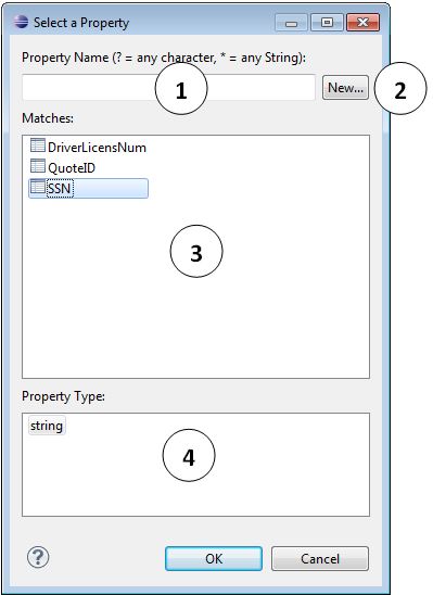
Property Name: Used to limit the items displayed in the Matches (3) list. Only those items that begin with the text in this filter will be displayed.
: Click this button to create a new WSDL property.
Matches: Displays the items that match the Property Name (1), or all items if the filter is blank.
Property Type: Displays the type of an item selected in the Matches (3) list.
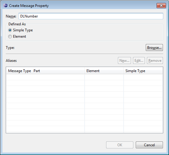
This dialog is used to create a new WSDL property and is displayed when you click the button in Section 3.6.4, “Select WSDL property” dialog.
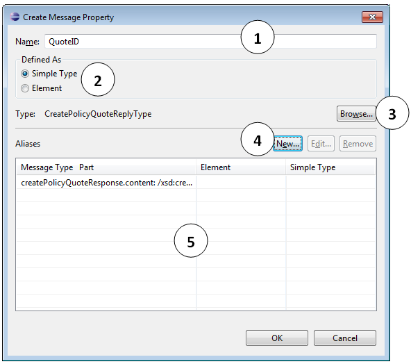
Name: Enter the name for the new property.
: Select how the property type will be defined.
Browse: Click this button to select the property type.
New: Click this button to create a new property alias.
Aliases: This list displays all property aliases defined for the property.
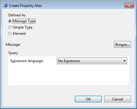
This dialog allows you to create a WSDL property alias for a selected property.
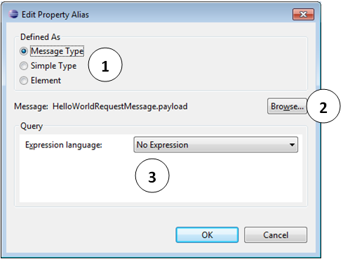
Defined As: Select how the property alias type will be defined.
: Click this button to select the property alias type.
Query: This editor allows you to use the XPath Expression Editor to define a query for the property alias.
Cheat sheets are part of the Eclipse Help framework, which provide interactive, step-by-step tutorials for plug-in tools. The BPEL Designer cheat sheet can be accessed by following → . You will then see the following screen:
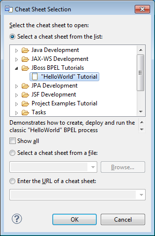
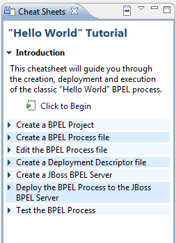
The cheat sheet will open in a separate view as show below. Click on the link to begin.
The BPEL Designer does not contribute any toolbar buttons, or main menu actions.
The context menu is activated when the right mouse button is clicked while the mouse is over an activity figure on the drawing canvas.
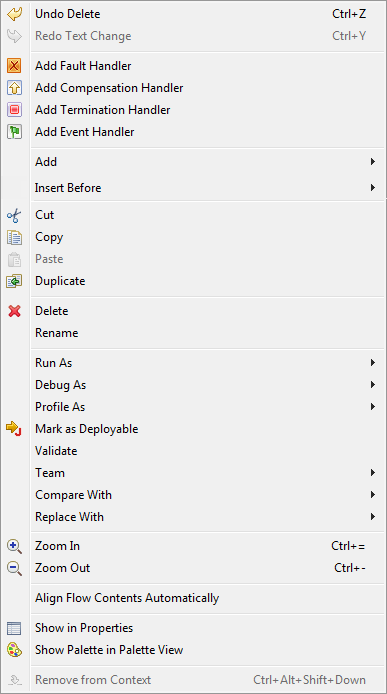
The and sub-menus contain the same actions. The sub-menu is displayed in the figure below:
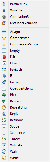
The items within the sub-menu appends the activity after the currently selected one, while those within the sub-menu insert the new activity before the current one.
This section lists all of the messages generated by the BPEL Validator. The SA (Static Analysis) column contains hyperlinks to the OASIS WS-BPEL 2.0 specification entry for each validation rule to which the message applies. It is possible that one message is applicable to more than one BPEL element or attribute, therefore all of the SA rules that are relevant are listed for each message.
Refer to the OASIS documentation linked in the SA column for a detailed explanation of the BPEL requirement, and for possible resolutions for the error.
Note
The substitution parameters (for example: {0} and {1}) are placeholders for the BPEL element, attribute or value identified by the Validator.
Table 4.1. Error messages
| Message text | SA |
|---|---|
| {1} "{2}" of type "{4}" is not compatible with WSDL message "{3}". | 00048 00058 00087 |
| The start activity <{0}> must be the first activity in the process. | 00056 |
| Standard fault "{1}" cannot be handled in <{0}> when exitOnStandardFaults is set to yes. | 00003 |
| The partner link "{1}" referenced from this <{0}> must have "{2}" defined. | 00037 |
| Target scope "{2}" does not exist. | 00077 |
| Target {3} "{2}" must have a compensationHandler or a faultHandler. | 00078 |
| {1,choice,0#Node|1#Activity} <{0}> must contain at least {5,choice,1#one node|1<{5} nodes} from {3} | 02002 |
| The <{1}> node present in this <{0}> has {2,choice,0# unspecified text value (is empty)| 1<="" td=""> | 00038 |
| <{3}> can only occur at most {5,choice,1#one time|1<{5} times} in parent {1,choice,0#node|1#activity} <{0}> | 02002 |
| <{1}> name "{2}" is already defined in this scope/process. | 00018 00023 00044 00064 00068 00069 |
| This <{0}> with name="{1}" was already defined previously | 00022 |
| Cannot import type "{1}" from location "{2}" | 01234 |
| The XSD type "{1}" of {2} "{3}" in this <{0}> is not a simple XSD type. | 00045 |
| This <{0}> uses undefined message part "{1}" in message type "{2}". | 00021 |
| There is no "{2}" message that is used by this <{0}> - {3,choice,0#node <{4}> |2#attribute "{4}"} must be omitted. | 00047 |
| Solicit-response operation "{4}" in portType "{3}" cannot be used in a BPEL process. | 00001 |
| XSD element <{0}> in import {1} conflicts with element of the same name in {2}. | 00014 |
| {1,choice,0#Node|1#Activity} <{0}> must have {2} {3,choice,0#node|1#activity|2#attribute} present. | 00080 00081 00083 00090 |
| The variable name "{1}" is used as a counter name in <{2}>. | 00076 |
| The link "{1}" used as a {0} is not defined in the enclosing flow. | 00065 |
| Scope "{1}" cannot have a <{2}> because because it is itself inside an FCT-hander. | 00079 |
| The <link> "{1}" has a control cycle where the source "{2}" has the target "{3}" as a preceding activity. | 00072 |
| <{0}> cannot be a child of <{1}>; it can only be a child of {2} | 02001 |
| The link "{1}" does not have a source. | 00066 |
| {0} attribute refers to an unsupported language URI {1} | 00004 |
| A catch for fault "{1}" already exist. | 00093 |
| Extension "{1}" is not supported by this implementation. | 00009 |
| {1,choice,0#Node|1#Activity} <{0}> must specify one {3,choice,0#node|1#activity|2#attribute} {2}. | 00081 00090 |
| The attribute {1} must be set to "{2}" on this <{0}> | 00057 |
| Attribute "{0}" must not be set on this <{1}> {2,choice,0#node|1#activity}. | 00046 |
| {3,choice,0#Node|1#Activity|2#Attribute} {2} must not be specified on {1,choice,0#node|1#activity} <{0}>. | 00090 |
| Attribute "{1}" cannot be set because {2} "{3}" is not an element. | 00042 |
| Immediately enclosed {0} "{1}" must have a unique name within the outer scope "{3}". | 00092 |
| "{1}" is set to "{2}" on this <{0}> {4,choice,0#node|1#activity} but it can only be set to {3} | 00017 00032 00046 00090 01001 01010 02003 02004 |
| The {1} of "{2}" is not compatible with {3} of "{4}" - {5} | 00043 |
| Message part "{1}" does not exist in message "{2}" | 00034 00054 |
| partnerLink "{1}" uses portType "{3}" (via partnerLinkType "{2}") which has an overloaded operation "{4}". | 00002 |
| Attribute "{1}" is not set on this <{0}> {2,choice,0#node|1#activity}. | 00000 00010 00024 00032 00046 00047 00081 00088 00090 01001 01004 01010 02003 02004 |
| The <{0}> activity named "{1}" must be in a fault, compensate, or termination handlers. | 00007 00008 |
| The "{1}" cannot be used on <{0}> that does not have {2} defined. | 00017 |
| <{0}> activity "{1}" specifies a portType "{2}", yet this portType does not match the portType derived from "{4}" of partnerLink "{3}" defined in WSDL "{5}" | 00005 |
| Isolated scope "{1}" cannot exist within another isolated scope (scope "{3}"). | 00091 |
| <{0}> activity "{1}" is trying to use partnerLink "{2}" which does not have a "{3}" defined. | 00084 |
| Part "{3}" must be specified on this <{2}> - activity <{1}> requires it. | 00050 |
| The targetNamespace {2} of the imported document is not the default namespace. | 00012 |
| This <{0}> activity is a start activity and cannot have an onAlarm component. | 00062 |
| The import namespace {1} and the imported document target namespace {2} do not match. | 00011 |
| The {1} start activities must share at least one correlation. | 00057 |
| Either "{1}" or "{2}" attribute is required on this <{0}> | 00019 00020 |
| The partner link "{1}" referenced from this <{0}> must have "{2}" defined. | 00035 00036 |
| The <{1}> activity named {0} must be in a fault handler. | 00006 |
| The part "{1}" is already specified in another <{0}>. | 00053 |
| The link "{1}" is not unique - the link "{2}" also makes an identical connection. | 00067 |
| The form of <{0}> is not valid (too many variants detected). | 00032 |
| The variable name "{0}" contains an illegal period (.) character. | 00024 |
| Notification operation "{4}" in portType "{3}" (via partnerLinkType "{2}") cannot be used in a BPEL process. | 00001 |
| The link "{1}" does not have a target. | 00066 |
| The link "{1}" crosses repeatable boundary on <{2}>. | 00070 |
| The "{0}" attribute of this <{1}> is set to "{2}" - it is not a valid NCName. | 00000 00024 01004 |
| Either <{1}> *or* attribute "{2}" must be specified on <{0}>. | 00051 00052 00055 00059 00063 00085 |
| The {1} "{2}" is not of messageType and a "part" is specified in this <{0}> node. | 00034 |
| "{1}" is set to "{3}" on this <{0}> {2,choice,0#|1#activity} but it cannot be resolved (check value of "{1}", imports, WSDLs or XSDs). | 00010 00017 00021 00032 00045 00081 00088 00090 02003 02004 |
| Link "{1}" must be outbound only; target activity must be outside of the enclosing <{2}>. | 00071 |
| Variable "{0}" must be have either messageType,element, or type defined. | 00025 |
| There is no start activity in process "{1}" | 00015 |
| {0} "{1}" must have "{2}" and/or "{3}" set. | 00016 |
Table 4.2. Error messages
| Message text | SA |
|---|---|
| The expression in <{0}> cannot be checked - no expression validator has been registered for language {1}. | 00029 00033 01000 |
| The {1} of simple type "{2}" is not compatible with {3} of simple type "{4}" - a BPEL runtime may provide an implicit conversion. | 00043 |
| The {3,choice,0#node|1#activity} <{0}> refers to a {1} (via the attribute "{2}") - this {1} needs to be defined correctly. | 00032 02003 02004 |
This document highlights the capabilities of BPEL Tools, as well as providing the steps required to create and configure BPEL process and deployment descriptor files. If you have questions or suggestions concerned both the documentation and tools behavior please visit the JBoss Tools Users forum.
All JBoss Tools release documentation you can find at http://docs.jboss.org/tools in the corresponding release directory.
The latest documentation builds are available at http://download.jboss.org/jbosstools/nightly-docs.