Drools is a business rule management system (BRMS) with a forward chaining inference based rules engine, more correctly known as a production rule system, using an enhanced implementation of the Rete algorithm.
In this guide we are going to get you familiar with Drools Eclipse plugin which provides development tools for creating, executing and debugging Drools processes and rules from within Eclipse.
Note:
It is assumed that you has some familiarity with rule engines and Drools in particular. If not, we suggest that you look carefully through the Drools Documentation.
Drools Tools comes bundled with the JBoss Tools set of Eclipse plugins. You can find instructions on how to install JBoss Tools in the Getting Started Guide.
The following table lists the main features of Drools Tools.
Table 1.1. Key Functionality of Drools Tools
| Feature | Benefit | Chapter |
|---|---|---|
|
Wizard for creating a new Drools Project |
The wizard provides a way to create a sample project to easily get started with Drools | Section 2.1, “Creating a Sample Drools Project” |
|
Wizards for creation of new Drools resources |
A set of wizards are provided with the Drools Eclipse tools to quickly create a new Rule resource, a new Domain Specific language, Decision Table and Business rule | Section 2.3, “Creating a New Rule” |
|
The Rule editor |
An editor that is aware of DRL syntax and provides content assistance and synchronizing with the Outline view | Section 4.3, “The Rule Editor” |
|
The Domain Specific Language editor |
An editor that provides a way to create and manage mappings from users language to the rule language | Section 4.1, “DSL Editor” |
|
The Rule Flow graphical editor |
The editor provides a way to edit the visual graphs which represent a process (a rule flow) | Section 4.2, “Flow Editor” |
Drools on JBoss.org
All JBoss Tools/JBDS documentation you can find on the documentation release page.
This chapter will cover the steps required to setup an executable sample Drools project in which rules can be used.
First, we suggest that you use Drools perspective which is aimed at work with Drools specific resources.
To create a new Drools project select → → → → . This will open the New Drools Project wizard, as shown in the figure below.
On the first page type the project name and click the button.
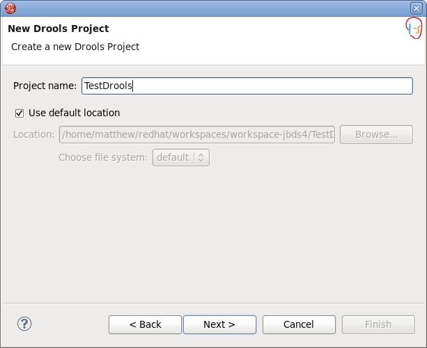
Next you have the choice to add some default artifacts to it like sample rules, decision tables or ruleflows and Java classes for them. Let's select first two check boxes and click the button.

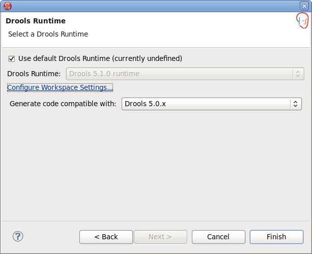
The next page asks you to specify a Drools runtime. If you have not yet set it up, you should do this now by clicking the link.
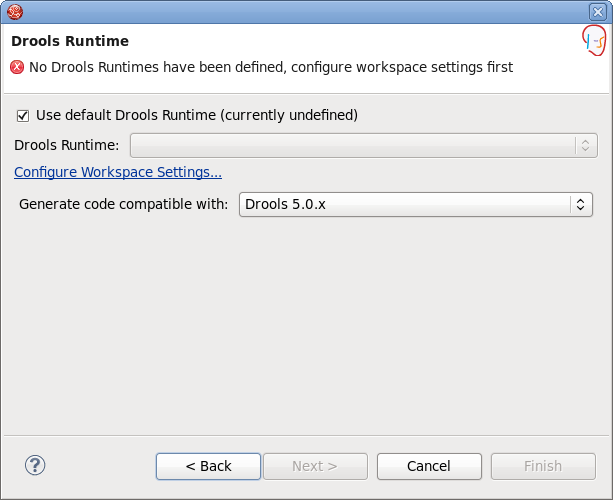
You should see the Preferences window where you can configure the workspace settings for Drools runtimes. To create a new runtime, click the button. The appeared dialog prompts you to enter a name for a new runtime and a path to the Drools runtime on your file system.
Note:
A Drools runtime is a collection of jars on your file system that represent one specific release of the Drools project jars. While creating a new runtime, you must either point to the release of your choice, or you can simply create a new runtime on your file system from the jars included in the Drools Eclipse plugin.
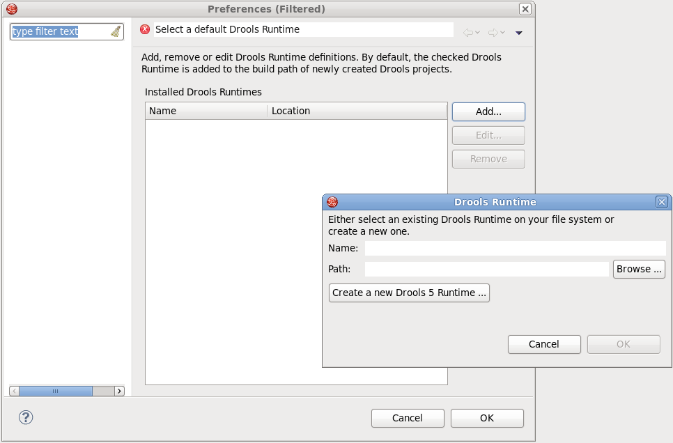
Let's simply create a new Drools 5 runtime from the jars embedded in the Drools Eclipse plugin. Thus, you should click the button, select the folder where you want this runtime to be created and click the button.
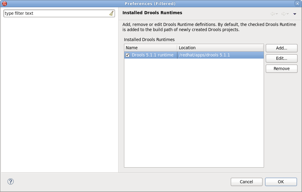
You will see the newly created runtime show up in your list of Drools runtimes. Check it and click the button.
Now click the to complete the project creation.
This will setup a basic structure, classpath, sample rules and test case to get you started.
Now let's look at the structure of the organized project. In the Package Explorer you should see the following:
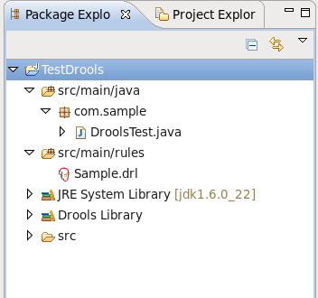
The newly created project contains an example rule file Sample.drl in the src/main/rules directory and an example java file DroolsTest.java that can be used to execute the rules in a Drools engine in the folder src/main/java, in the com.sample package. All the others jar's that are necessary during execution are also added to the classpath in a custom classpath container called Drools Library.
Tip:
Rules do not have to be kept in Java projects at all, this is just a convenience for people who are already using Eclipse as their Java IDE.
Now we are going to add a new Rule package to the project.
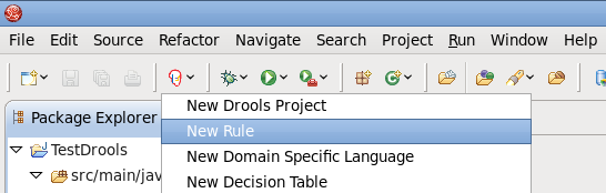
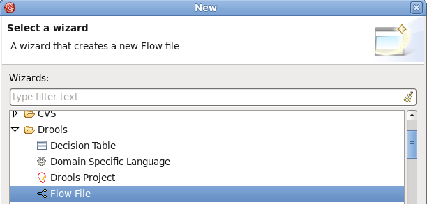
You can either create an empty text .drl file or make use of the special New Rule Package... wizard to do it.
To open the wizard select → → or use the menu with the JBoss Drools icon on the toolbar.
On the wizard page first select /rules as a top level directory to store your rules and type the rule name. Next specify the mandatory rule package name. It defines a namespace that groups rules together.
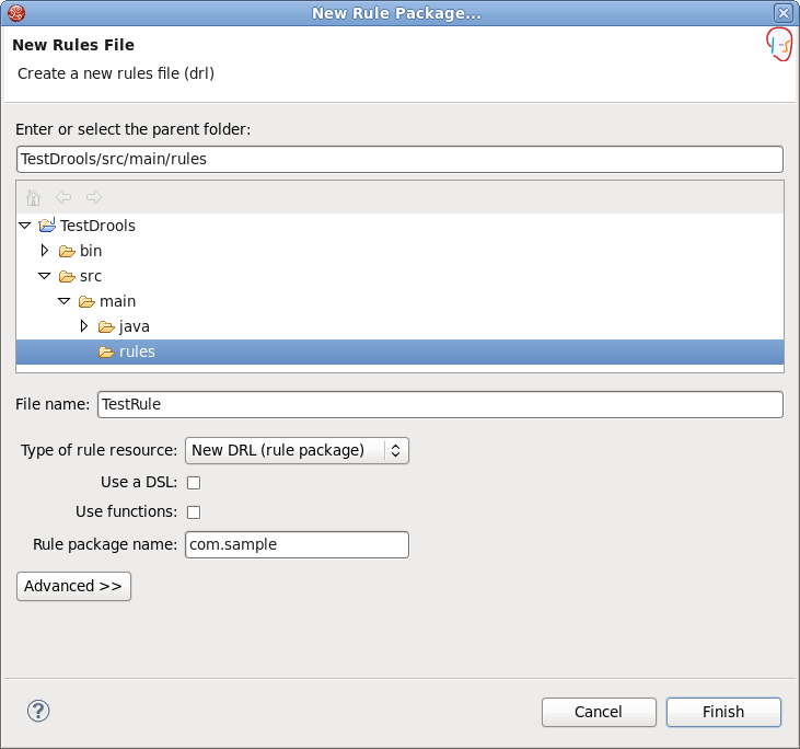
As a result the wizard generates a rule skeleton to get you started.

This chapter describes how to debug rules during the execution of your Drools application.
This section will focus on how to add breakpoints in the consequences of your rules.
Whenever such a breakpoint is encountered during the execution of the rules, the execution is halted. Once the execution is halted, it's possible to inspect the variables known at that point and use any of the default debugging actions to decide what should happen next (step over, continue, etc). To inspect the content of the working memory and agenda the Debug views can be used.
To create breakpoints in the Package Explorer view or Navigator view of the Drools perspective, double-click the selected .drl file to open it in the editor. In the example below we opened Sample.drl file.
You can add and remove rule breakpoints in the .drl files in two ways, similar to the way breakpoints are added to Java files:
Double-click the ruler in the Rule editor at the line where you want to add a breakpoint.
Tip:
Note that rule breakpoints can only be created in the consequence of a rule. Double-clicking on a line where no breakpoint is allowed will do nothing.
A breakpoint can be removed by double-clicking the ruler once more.
Right-click the ruler. Select the action in the context menu. Choosing this action will add a breakpoint at the selected line or remove it if there is one already.

The Debug perspective contains a Breakpoints view which can be used to see all defined breakpoints, get their properties, enable/disable or remove them, etc. You can switch to it by navigating to → → → .
Drools breakpoints are only enabled if you debug your application as a Drools Application. To do this you should perform one of the actions:
Select the main class of your application. Right click it and select → .
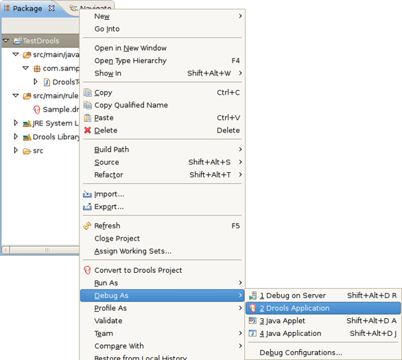
Alternatively, you can also select → to open a new dialog for creating, managing and running debug configurations.
Select the Drools Application item in the left tree and click the button (leftmost icon in the toolbar above the tree). This will create a new configuration with a number of the properties already filled in (like the Project and Main class) based on main class you selected in the beginning. All properties shown here are the same as any standard Java program.

Tip:
Remember to change the name of your debug configuration to something meaningful.
Next click the button on the bottom to start debugging your application.
After enabling the debugging, the application starts executing and will halt if any breakpoint is encountered. This can be a Drools rule breakpoint, or any other standard Java breakpoint. Whenever a Drools rule breakpoint is encountered, the corresponding .drl file is opened and the active line is highlighted. The Variables view also contains all rule parameters and their value. You can then use the default Java
debug actions to decide what to do next (resume, terminate, step over, etc). The debug views can also be used to determine the contents of the working memory and agenda at that time as well (you don't have to select a working memory now, the current executing working memory is automatically shown).
A domain-specific language is a set of custom rules, that is created specifically to solve problems in a particular domain and is not intended to be able to solve problems outside it. A DSL's configuration is stored in plain text.
In Drools this configuration is presented by .dsl files that can be created selecting → → → → from the projects context menu.
DSL Editor is a default editor for .dsl files:
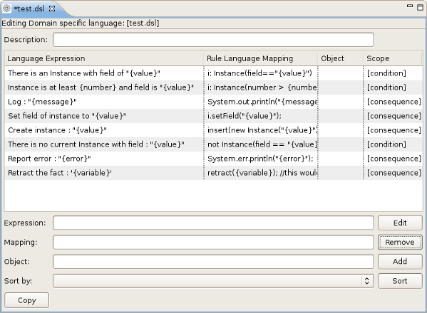
In the table below all the components of the DSL Editor page are described:
Table 4.1. DSL Editor Components.
| Components | Description |
|---|---|
| Description | User's comments on a certain language message mapping |
| Table of language message mappings | The table is divided into 4 rows:
|
| Expression | Shows the language expression of the selected table line (language message mapping). |
| Mapping | Shows the rule of language mapping for the selected table line (language message mapping). |
| Object | Shows the object for the selected table line (language message mapping) |
| Sort By | Using this option you can change the sorting order of the language message mappings. To do this select from the drop down list the method of sorting you want and click the button. |
| Buttons |
|
This wizard can be opened by double clicking some line in the table of language message mappings or by clicking the button.
On the picture below you can see all the options the Edit Language Mapping Wizard will allow you to change.
Their names as well as the meaning of the options are correspond to the rows of the table (see the Table of language message mappings row in Table 4.1, “DSL Editor Components.”).
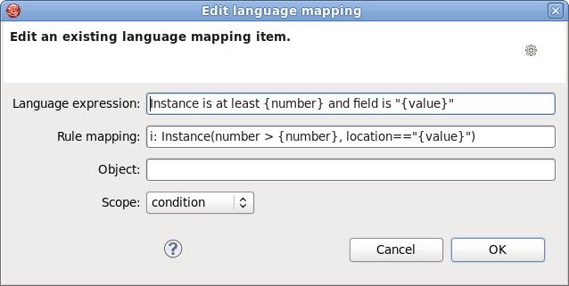
To change the mapping a user should edit the appropriate options and finally click the button.
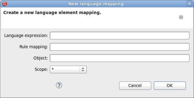
This wizard is equal to the wizard described in Section 4.1.1, “Edit language mapping Wizard”. It can be opened by clicking the button.
The only difference is that instead of editing the information you should enter new one.
Drools tools also provides the ability to define the order in which rules should be executed. The Ruleflow file allows you to specify the order in which rule sets should be evaluated using a flow chart. This allows you to define which rule sets should be evaluated in sequence or in parallel as well as specify the conditions under which rule sets should be evaluated.
Ruleflows can be set only by using the graphical flow editor which is part of the Drools plugin for Eclipse. Once you have set up a Drools project,you can start adding ruleflows. Add a ruleflow file(.rf) by clicking on the project and selecting → → → :
By default these ruleflow files (.rf) are opened in the graphical Flow editor. You can see this in the picture below.
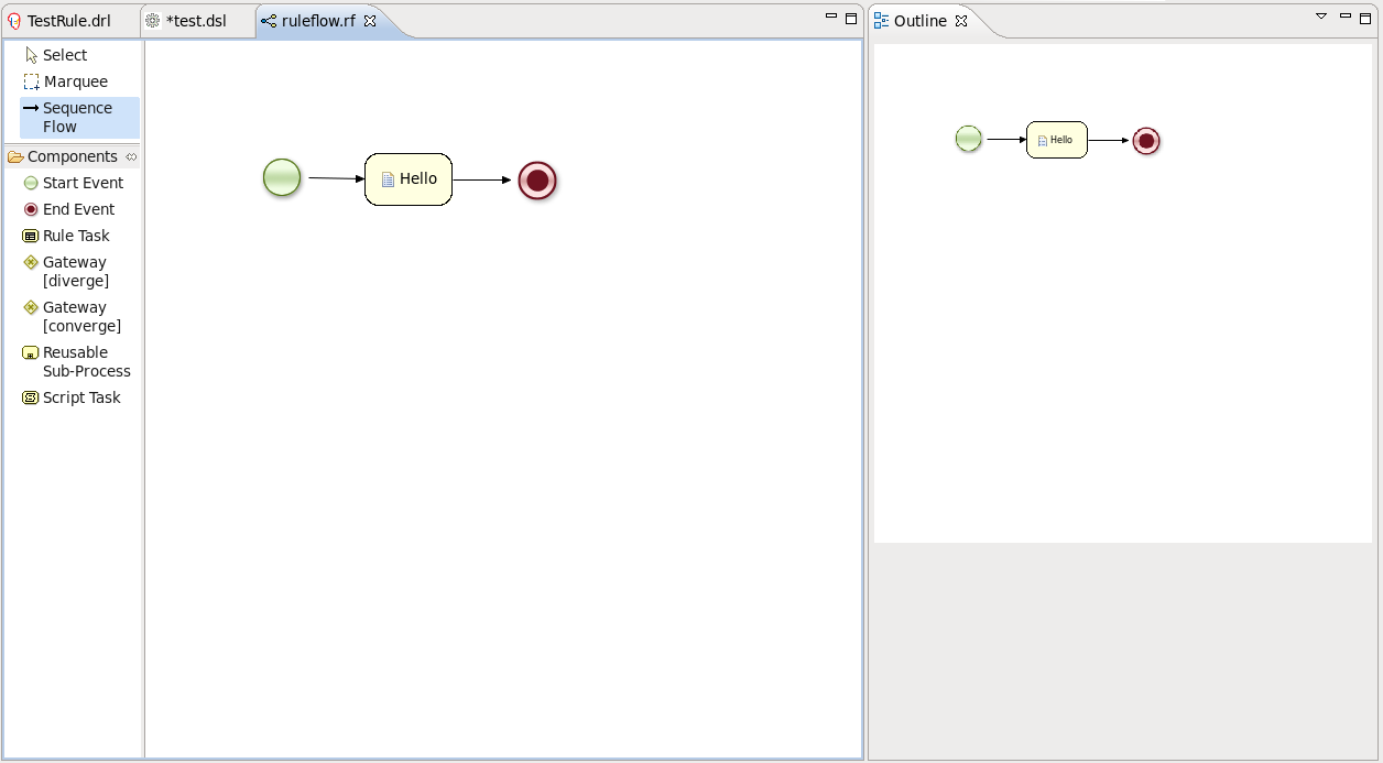
The Flow editor consists of a palette, a canvas and an outline view. To add new elements to the canvas, select the element you would like to create in the palette and then add it to the canvas by clicking on the preferred location.
Clicking on the Select option in the palette and then on the element in your ruleflow allows you to view and set the properties of that element in the Properties view.

The Outline view is useful for big complex schemata where not all nodes are seen at one time. So using your Outline view you can easily navigate between parts of a schema.

Flow editor supports three types of control elements. They are:
Table 4.2. Flow Palette Components.Part 1
| Component Picture | Component Name | Description |
|---|---|---|

| Select | Select a node on the canvas |

| Marquee | Is used for selecting a group of elements |

| Sequence Flow | Use this element to join two elements on the canvas |
Currently, ruleflow supports seven types of nodes. In the table below you can find information about them:
Table 4.3. Flow Palette Components.Part 2.
| Component Picture | Component Name | Description |
|---|---|---|

| Start Event | The start of the ruleflow. A ruleflow should have exactly one start node. The Start Event can not have incoming connections and should have one outgoing connection. Whenever the ruleflow process is started, the execution is started here and is automatically proceeded to the first node linked to this Start Event |

| End Event | A ruleflow file can have one or more End Events. The End Event node should have one incoming connection and can not have outgoing connections. When an end node is reached in the ruleflow, the ruleflow is terminated (including other remaining active nodes when parallelism is used). |

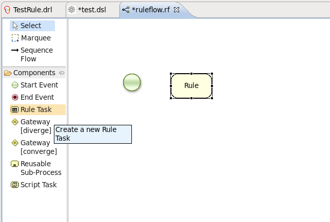
| Rule Task | Represents a set of rules. A Rule Task node should have one incoming connection and one outgoing connection. The RuleFlowGroup property which is used to specify the name of the ruleflow-group that represents the set of rules of this Rule Task node. When a Rule Task node is reached in the ruleflow, the engine will start executing rules that are a part of the corresponding ruleflow-group. Execution automatically continues to the next node when there are no more active rules in this ruleflow-group. |

| Gateway[diverge] | Allows you to create branches in your ruleflow. A Gateway[diverge] node should have one incoming connection and two or more outgoing connections. |
|
| Gateway[converge] | Allows you to synchronize multiple branches. A Gateway[converge] node should have two or more incoming connections and one outgoing connection. |

| Reusable Sup-Process | Represents the invocation of another ruleflow from this ruleflow. A subflow node should have one incoming connection and one outgoing connection. It contains the property processId which specifies the id of the process that should be executed. When a Reusable Sup-Process node is reached in the ruleflow, the engine will start the process with the given id. The subflow node will only continue if that subflow process has terminated its execution. Note that the subflow process is started as an independent process, which means that the subflow process will not be terminated if this process reaches an end node. |

| Script Task | Represents an action that should be executed in this ruleflow. An Script Task node should have one incoming connection and one outgoing connection. It contains the property "action" which specifies the action that should be executed. When a Script Task node is reached in the ruleflow, it will execute the action and continue with the next node. An action should be specified as a piece of (valid) MVEL code. |
The Rule editor works on files that have a .drl (or .rule in the case of spreading rules across multiple rule files) extension.
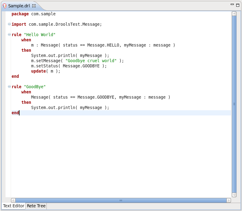
The editor follows the pattern of a normal text editor in eclipse, with all the normal features of a text editor:
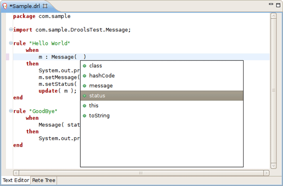
While working in the Rule editor you can get a content assistance the usual way by pressing Ctrl+Space.
Content Assist shows all possible keywords for the current cursor position.

Content Assist inside of the Message suggests all available fields.
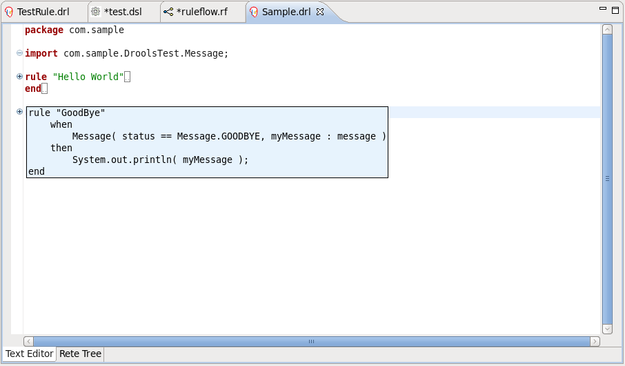
Code folding is also available in the Rule editor. To hide and show sections of the file use the icons with minus and plus on the left vertical line of the editor.
The Rule editor works in synchronization with the Outline view which shows the structure of the rules, imports in the file and also globals and functions if the file has them.
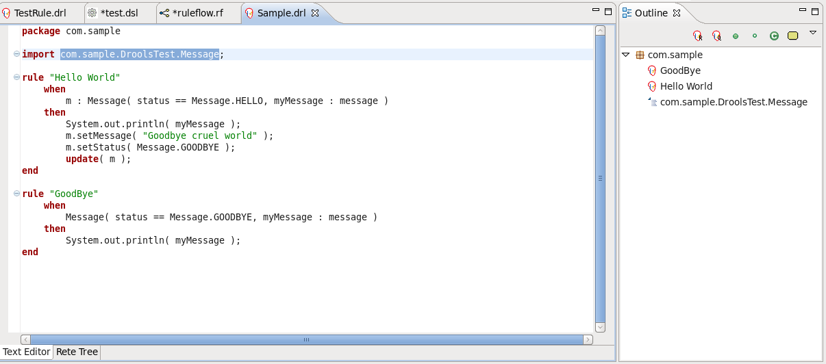
The view is updated on save. It provides a quick way of navigating around rules by names in a file which may have hundreds of rules. The items are sorted alphabetically by default.
The Rete Tree view shows you the current Rete Network for your .drl file. Just click on the Rete Tree tab at the bottom of the Rule editor.

Afterwards you can generate the current Rete Network visualization. You can push and pull the nodes to arrange your optimal network overview.
If you have a large number of nodes, select some of them with a frame. Then you can pull groups of them.
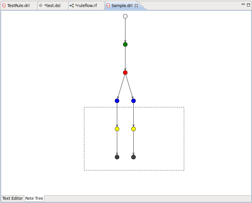
You can zoom in and out the Rete tree in case not all nodes are shown in the current view. For this use the combobox or and icons on the toolbar.

Note:
The Rete Tree view works only in Drools Rule Projects, where the Drools Builder is set in the project properties.
We hope, this guide helped you to get started with the JBoss BPMN Convert module. For additional information you are welcome on JBoss forum.