A scenario is essential a representation of a particular path through a business process.
Business processes usually have number paths that can be taken during a transaction. A simple example is when purchasing some goods, where one scenario maybe that the customer successfully completes their purchase, after receiving an appropriate credit rating. Another scenario may be that the customer has a bad credit rating and therefore the business transaction must reject the customer's purchase request.
In most business transactions there will be many different variations that could occur, and by defining these scenarios it is possible for business stakeholders to clearly define their needs (i.e. requirements), and for those scenarios to be used in subsequent phases of the software development lifecycle to ensure the system being built meets those needs.
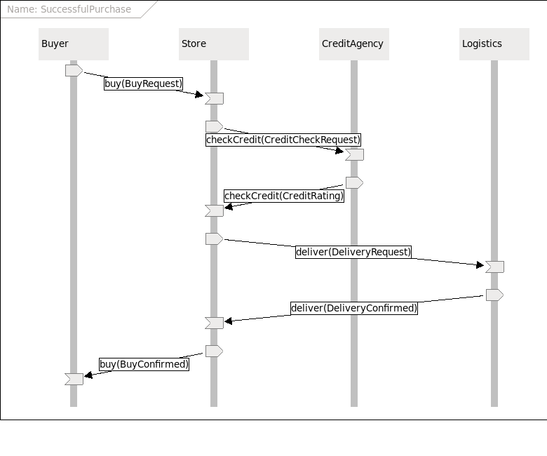
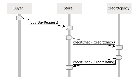
An example of a scenario representing a successful purchase is:
After creating an Eclipse project, and optionally a sub-folder to contain the scenarios being created, select the "New->Other..." menu item on the context menu for the project or folder in which the scenario be created. This will show the following dialog:
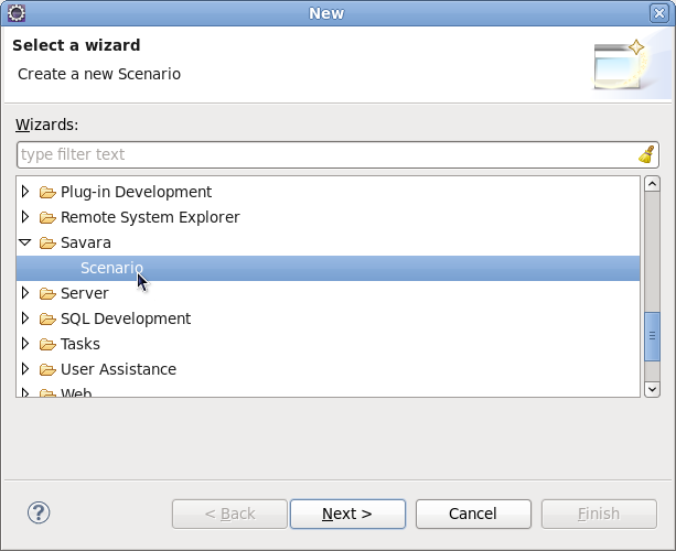
Select the Savara->Scenario item and then press the Next button, when you will be requested to enter the name of the scenario file, and then press the Finish button.
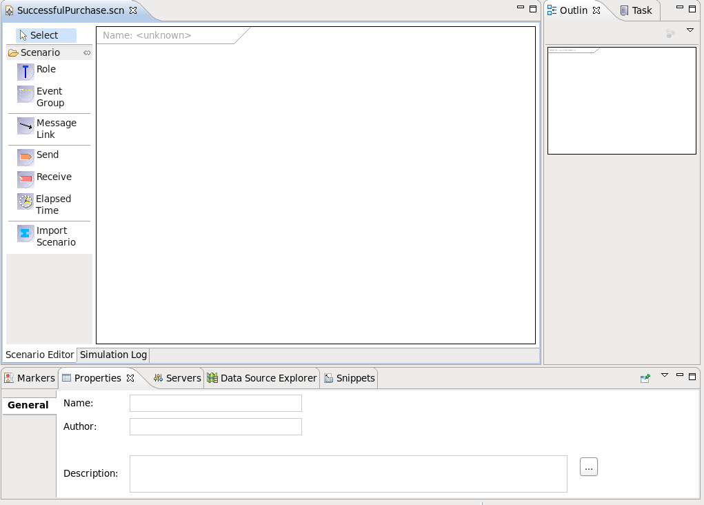
When the scenario is first created, it will have a blank canvas. If the Properties view is selected (at the bottom of the Eclipse window), and then the canvas is selected, the Properties view will show the properties associated with the scenario, i.e. name, author and description. These fields should be complete to provide a clear identification of the scenario, its owner and the details of what use case it represents in the context of the system being built.
A Role is a participant within the scenario. It represents an entity that is actively involved in performing tasks to help achieve a particular business goal.
We currently assume that there is a one-to-one mapping between a role and a service being implemented, although this will not always be the case. On some occasions a role may begin as a high level concept, which may evolve through the design process to become multiple services, possibly implemented by a single top level composite service associated with the role. It is also possible that a role may represent a human (i.e. manual) task.
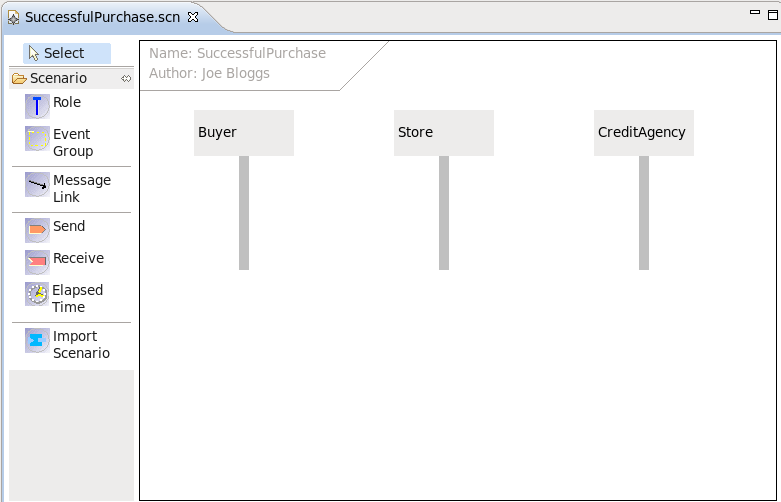
To add a new role to the scenario, simply select the Role item from the left hand palette and click on the canvas. The role is displayed as a vertical line, with a box at the top containing the role name (which is "<unknown>" until a valid value is defined).
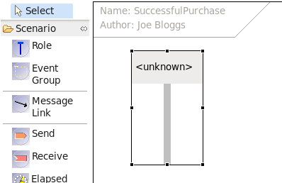
When the role is selected, the Properties view will show the property fields appropriate for this item. At this point, the role should be named. For example, in our example scenario we will create three roles, Buyer, Store and CreditAgency:
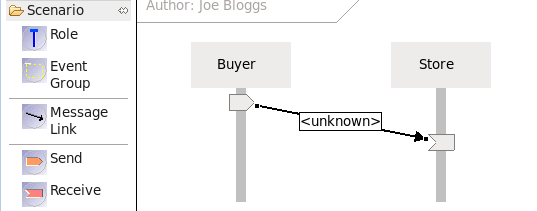
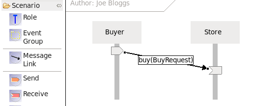
An interaction represents the exchanging of a message from one role to another role(s).
This is achieve by dragging a link between the 'originating' (or 'source') role to the 'destination' (or 'target') role. This will cause 'send' and 'receive' message events to be added to the source and target roles, with a link between drawn between them.
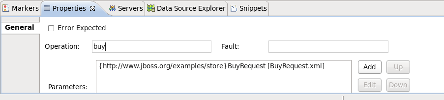
While the link is selected, go to the Properties view to set the relevant properties for the message.
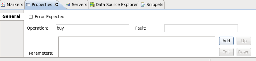
The "Error Expected" property is a checkbox that can be used to indicate that this message is expected to be incorrect when used for simulating or testing against other artifacts.
The "Operation" field represents the name of the operation being performed. In cases where the target architecture is message oriented, this may not seem necessary, however it can be useful to clarify the purpose of the interaction.
The optional "Fault" field is used to provide a fault name for the interaction, in situations where the message exchange represents a fault response.
The "Parameters" list represents the one or more pieces of information that should be exchanged with the message. Pressing the 'Add' button will show another dialog window:
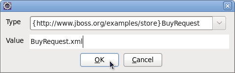
The "Type" field represents a fully qualified type name. The value within the curly braces defines the namespace, and the remaining text is the 'local part'.
The "Value" field represents a path to the file containing the example message value. The path can define a relative path, as in the image above, from the scenarios location. So this example indicates that the message value file ( BuyRequest.xml ) is in the same folder as the scenario file that is referencing it.
Once the parameter has been defined, it will be displayed in the parameters list as above and the text associated with the message link will be updated to summarize the information.
It is also possible to select the individual send and/or receive message events from the palette and attach them to the appropriate roles, with or without a link to connect them. For example, if a 'send message event' is placed on a Role, with the associated message information, this will indicate that the role sends a message but the intended recipient does not get it for some reason.
This is an example of where we want to represent an invalid (or negative) use case. Although this may seem counter intuitive, it can be useful to be able to specify anti use cases, as a way to document situations that we don't want to be implemented. Through the use of the 'Error Expected' field (associated with the Message Link properties) it is also possible to identify which parts of these negative scenarios should observe errors, and therefore can be used for automated testing.
As previously described, scenarios allow us to represent different paths that may occur through a business process.
Although most of these paths will be based on actions taken by the various roles involved in the scenario, occasionally scenarios also need to be able to indicate what should happen when no action occurs - i.e. a 'time out' situation.
As we are building up our scenario, if appropriate, we can introduce an 'elapsed time' event into the scenario. So if we start with an interaction to the CreditAgency, e.g.
We then want to be able to define a scenario to represent the case where the CreditAgency does not respond within a certain time period. To add an 'elapsed time' event, simply select the "Elapsed Time" icon from the palette and select the vertical location on the diagram where the event should be added. It will introduce a region horizontally across all roles.
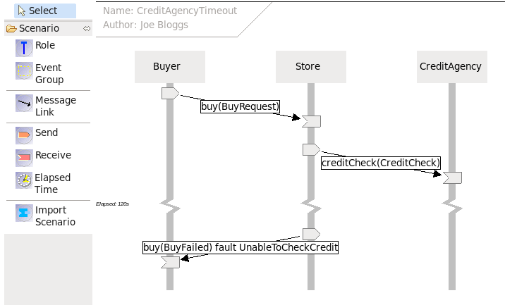
Figure 2.12. Scenario representing the case where a timeout occurs, and the behaviour that should follow
This can be used to document that the maximum timeout should be 2 minutes (120 seconds), and also used during simulation/service testing to ensure the implementation correctly handles the timeout.
Scenarios, like any other model, can benefit from reuse.
This section shows how scenarios can be composed, to allow common "sub" scenarios to be reused as part of high level scenarios. The benefit of this approach is the maintenance of scenarios, where a common sequence of messages exchanges between the same set of roles, is relevant to many use cases. When it becomes necessary to make a change to this common scenario, it only needs to be performed in one location to be applicable to all use cases.
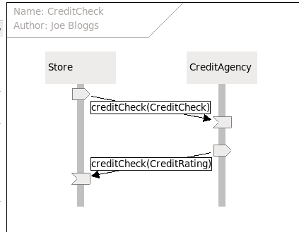
The following is a scenario related to performing the credit check:
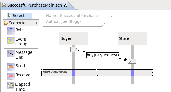
This can then be used within a higher level version of the SuccessfulPurchase scenario:
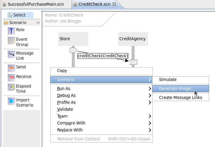
The Scenario diagram can be generated as an image for inclusion in documents or simply to be printed.
To generate the image, select the "Scenario->Generate Image" menu item from the context menu associated with the scenario background:
This will display a file dialog to select the name, type (e.g. bmp, png, jpeg, etc) and location for the generated image file.
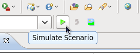
The scenario simulation is triggered either using the button on the toolbar, or the "Scenario->Simulate" menu item on the context menu associated with the diagram background:
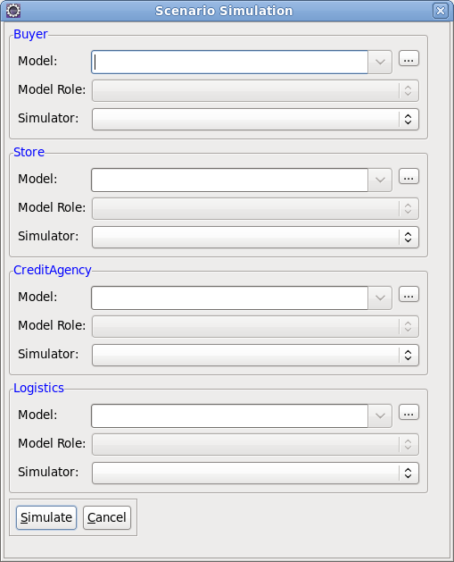
This will display a dialog window to capture information used to simulate each of the roles defined in the scenario, e.g.
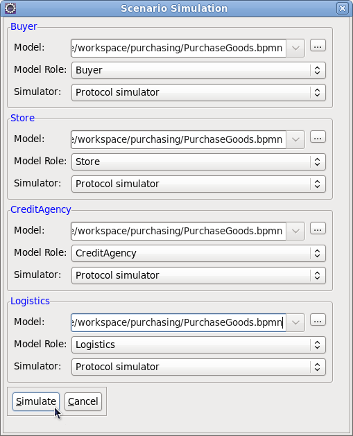
The next step is to associate a model with one of the roles. This is achieved by selecting the "..." button next to the model field, which allows the user to select the model file. A model file can be anything - if the file is a supported representation, then its selection will result in the "Model Role" and "Simulator" combo boxes being populated with valid values.
The "Model Role" field displays a list of roles that are derived from the selected model. This enables the role name defined in the scenario (shown in blue associated with the border), to be associated with the role within the model.
The "Simulator" field displays the list of simulators that can be used to validate the scenario against the model. Some model types may have more than one simulator implementation - this will be discussed more in subsequent sections. When a new simulator is selected, then the "Model Role" list will be updated based on the list of model roles determined by that simulator.
Once the first model has been selected, the user will be prompted to ask whether the same model should be used for all roles in the scenario.
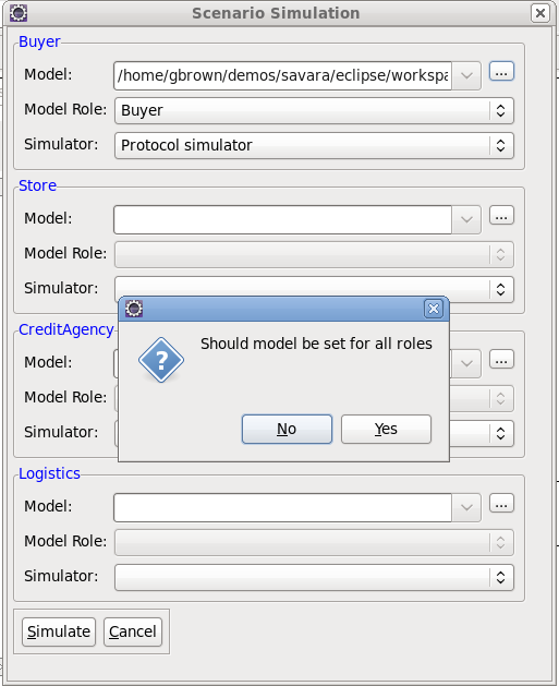
If the model that was selected was specific to the role (i.e. it represented an implementation just relevant to the particular role), then press the No button. However if the model is associated with more than one role in the scenario (i.e. a choreography), then pressing the 'Yes' button populates the simulation dialog, using the "best guess" to select the model role relevant for the scenario role.
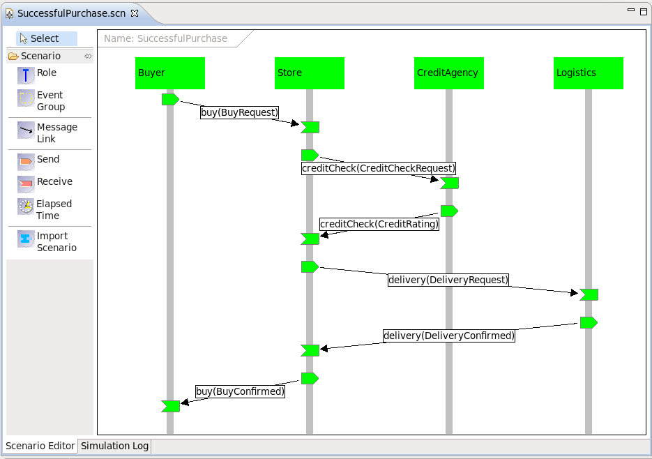
When the "Simulate" button is pressed, then message events (associated with the specific roles) in the scenario are simulated against the models specified in the dialog. If the message event is valid, its node will be displayed in green. If however the event is unexpected, then it will be displayed in red. When this occurs, either select the role, message link or particular red node, and then pick the "Simulation Log" tab at the bottom, to see log information returned from the simulator regarding the erroneous role or events.
NOTE: If a scenario 'message event' has been marked as 'Error Expected', then it will be displayed with a red border - but when simulated, the color within the message event node will be green if the node failed as expected, but red if the event did not generated an error.
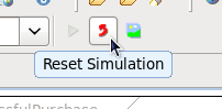
Finally the simulation can be reset,
Version 2.1 of the tools introduces a preview feature that will take a group of scenarios, representing different valid paths through a business process, and generate the appropriate BPMN2 Choreography Model (i.e. Architecture) and BPMN2 Process Models (i.e. designs - one per distinct role in the scenarios).
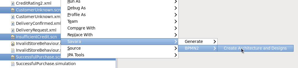
To perform this action, select all of the relevant scenarios and then select the "Savara->BPMN2->Create Architecture and Designs" menu item, as shown in the following figure:
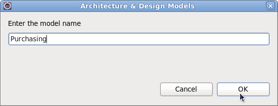
Once selected, this menu item will display a dialog to obtain the main name of the models to be created:
When the "OK" button is pressed, this will cause the Choreography and Process Models to be created:
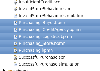
The Choreography is defined in
Purchasing.bpmn
, with each role having a process model named
Purchasing_<RoleName>.bpmn
.