Go To: Table of Contents
As described briefly in Chapter 1, you can test your models in by using the
Preview Data action ![]() . You can also test your models via your deployable VDB. These two options will be described in detail in this chapter
as well as managing your required connector bindings.
. You can also test your models via your deployable VDB. These two options will be described in detail in this chapter
as well as managing your required connector bindings.
In order to test your data, the Designer requires applicable connector information. This information is stored in the properties of a Connector Binding. The Designer provides a Connectors view for managing your bindings and this section summarizes its features and capabilities.
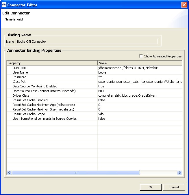
To edit properties of a connector binding, you can either select the binding and edit the properties in the Properties view, or select the Edit action and open the Connector Editor dialog presented below. Select the applicable 'Value' to activate the individual value editor.
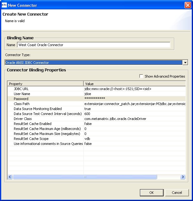
Create a new connector binding by either selecting the New Connector Binding action in the Connectors view toolbar or right-click select the same action from the context menu. If connector types are displayed in the Connectors view, you can select a connector type first, then select the New Connector Binding action. This will pre-select the type in the New Connector dialog. The action will launch the New Connector dialog shown below. Provide a valid binding name, select desired connector type, enter your custom properties and click OK to create you new connector binding.
In order to preview your data, you'll need to bind your source models to valid connectors. If you import your source from JDBC, your connector binding will be created during the import process and your source automatically bound to that connector binding.
You can bind, unbind or change source bindings in a couple of ways.
To bind a source, you can:
Select a model in the Model Explorer view select the Modeling > Connector >> Bind action. This action presents a dialog for selecting your desired existing Connector binding. Select a binding and click OK.
Select a model in the Model Explorer view and drag the model into the Connectors view and drop into the desired existing Connector binding.
To unbind a source:
Select the source model in Connectors view and right-click select the Unbind action.
Select the model in the Model Explorer view and select the Modeling > Connector >> Unbind action.
You can import your custom connector types and bindings into Designer. These bindings can be in the form of a *.cdk file (i.e. exported from Designer) or from a *.caf (connector archive file) defined during connector development.
To import import connector types and/or bindings:
Step 1 - Select the Import Connectors (*.cdk, *.caf) action
 located in the Connectors view
toolbar or in the right-click menu.
located in the Connectors view
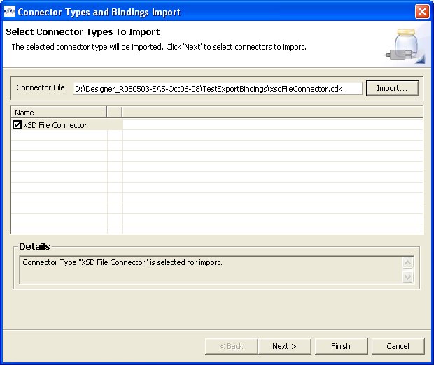
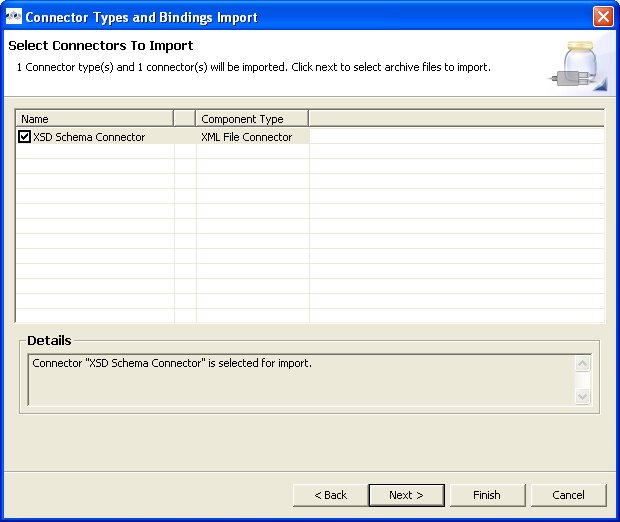
toolbar or in the right-click menu.Step 2 - In the first wizard page, Select the Import... button to select your *.cdk or *.caf file on your local file system. This page presents a summary of the custom connector types defined in your cdk/caf file. Use the check-boxes in the table to choose which types to import. Select Next> to view additional binding and jar import options or click Finish (if enabled) to import selected types and all associated bindings and connectors jars. Note: This wizard page contains a details panel which displays status messages for selected connector types.
Step 3 - The second wizard page contains connector types defined in your cdk/caf file. Use the check-boxes in the table to choose which bindings to import. Select Next> to view additional jar import options or click Finish (if enabled) to import selected types, bindings and all associated connectors jars. Note: Note: This wizard page contains a details panel which displays status messages for selected connector types.
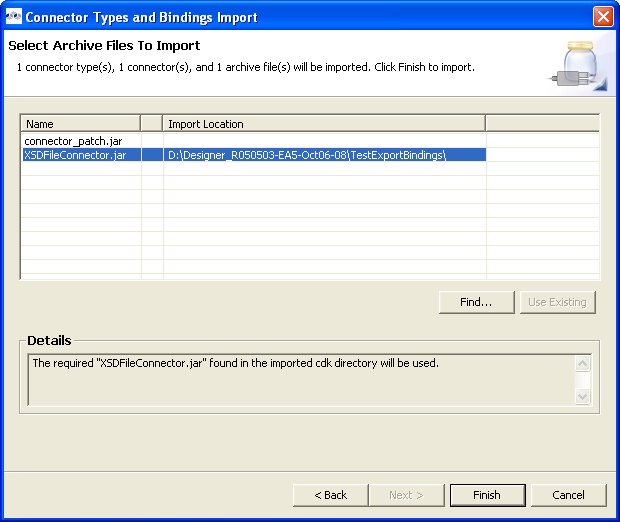
Step 4 - The last wizard page contains connector jars defined either in your caf file or jars located in the same file system folder as the initial cdk file. If while importing a cdk file the required jars are not present in the selected file system folder, select the Find... button to locate and select the required jar from your local file system.
Notes
1) This wizard page contains a details panel which displays status messages for selected connector types.
2) The Finish button will not enable until all custom connector jars are identified and defined. These jar files are defined in the classPath property for both connector bindings and connector types.
Step 5 - Click Finish to complete the import.
You can export your custom connector bindings from Designer into a *.cdk file.
To export connector bindings:
Step 1 - Select one or more Connector Bindings in the Connectors view.
Step 2 - Select the Export Connectors (*.cdk) action
 located in the Connectors view
toolbar or in the right-click menu.
located in the Connectors view
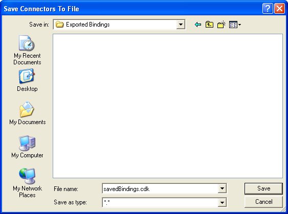
toolbar or in the right-click menu.Step 3 - In the wizard, select a location on your local file system and specify a *.cdk file name (default is: savedBindings.cdk)
Step 4 - Click Finish to complete the import.
After creating your models, you can test them by using the
Preview Data action ![]() . By selecting a desired table object and
executing the action, the results of a simple query will be displayed
in the Preview results view. This
action is accessible throughout the
Designer in various view toolbars and context menus.
. By selecting a desired table object and
executing the action, the results of a simple query will be displayed
in the Preview results view. This
action is accessible throughout the
Designer in various view toolbars and context menus.
There are two requirements for previewing your data: the selected object must be one of several previewable model object types and all source models within the model dependency tree must be bound to connector bindings. Model objects that can be previewed include: relational tables and views (including tables involving access patterns), relational procedures, Web service operations and XML document staging tables.
Note that any virtual table, view or procedure is previewable as long as all "physical" source models are bound via connector bindings. (See Connectors view )
Testing Your Transformations
When editing transformation SQL in the Transformation Editor, a special Preview data action is provided in the
editor tool-bar ![]() .
.
You can change your transformation SQL, re-validate and preview your the data for your modified SQL.
The following sections provide steps for previewing your data. Note that all steps assume that all source models referenced by your models, either directly or through dependencies, are bound to connector bindings.
To preview a relational table, relational view or staging table:
Step 1 - Select a relational table or view in the Model Explorer or diagram. The table or view can be in a view model as well as a source model. Staging tables are not visible in the Model Explorer, so you need to open the mapping diagram and select it there.
Step 2 - Right-click select the Preview Data action
 . You can also select the same action in the tool-bar of either
the Model Explorer or diagram.
. You can also select the same action in the tool-bar of either
the Model Explorer or diagram. Step 3 - Your query results will be displayed in the Preview results view. The view will automatically open or get focus if not visible in your perspective.
To preview a relational table or view with access pattern:
Step 1 - Select a relational table or view in the Model Explorer or diagram that contains an access pattern. The table or view can be in a view model as well as a source model.
Step 2 - Right-click select the Preview Data action
. You can also select the same action in the tool-bar of either
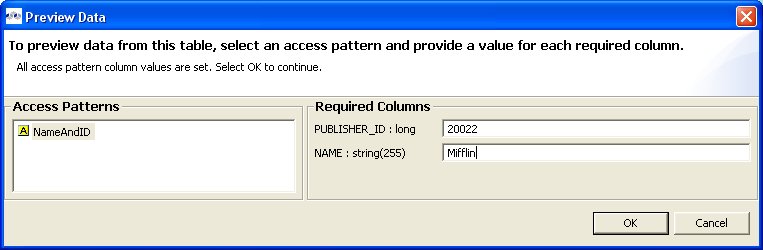
the Model Explorer or diagram. Step 3 - A column input dialog is presented. Select each access pattern and enter a value for each required column. Note that if data entered does not match the column datatype (String, integer, etc...), an error message will be displayed in the dialog header. When all required values are entered, click the OK button to execute the query.
Step 4 - Your query results will be displayed in the Preview results view. The view will automatically open or get focus if not visible in your perspective.
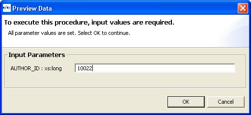
To preview a relational procedure:
Step 1 - Select a relational procedure in the Model Explorer or diagram. The procedure can be in a view model as well as a source model.
Step 2 - Right-click select the Preview Data action
. You can also select the same action in the tool-bar of either
the Model Explorer or diagram. Step 3 - An input parameter input dialog is presented. Enter a valid value for each parameter. Note that if data entered does not match the parameter datatype (String, integer, etc...), an error message will be displayed in the dialog header. When all required values are entered, click the OK button to execute the query.
Step 4 - Your query results will be displayed in the Preview results view. The view will automatically open or get focus if not visible in your perspective.
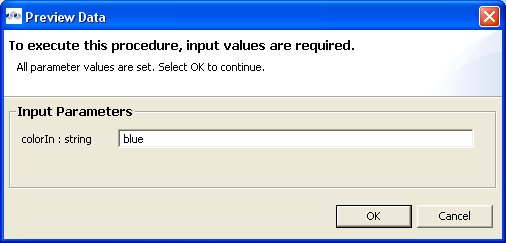
To preview a Web service operation:
Step 1 - Select a Web service operation in the Model Explorer or diagram. The operation can be in a view model as well as a source model.
Step 2 - Right-click select the Preview Data action
. You can also select the same action in the tool-bar of either
the Model Explorer or diagram. Step 3 - An input parameter input dialog is presented. Enter a valid value for each parameter. Note that if data entered does not match the parameter datatype (String, integer, etc...), an error message will be displayed in the dialog header. When all required values are entered, click the OK button to execute the query.
Step 4 - Your query results will be displayed in the Preview results view. The view will automatically open or get focus if not visible in your perspective.
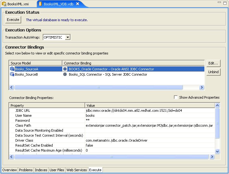
To execute a query against your VDB:
Step 1 - In the Model Explorer, double-click a VDB, or select one and choose Open action to open a VDB Editor.
Step 2 - Select the Execute tab. If connector bindings are missing for any source models, the Execute button will be disabled. Edit your bindings to create/select bindings for your models.
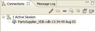
Step 3 - Select the Execute button to establish a connection and open the SQL Explorer perspective. Your VDB should now be connected via the connector bindings defined previously. Verify the connection in the Connections view.
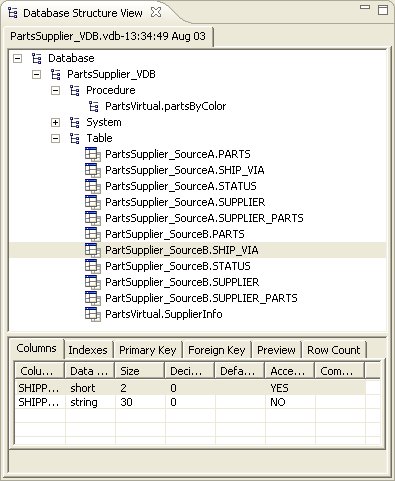
Step 4 - In the Database Structure view (upper left), expand the Table node to list the tables in your VDB.
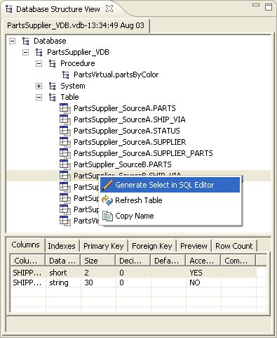
Step 5 - Select one of the tables and do a right click. Select the Generate Select in SQL Editor menu item.
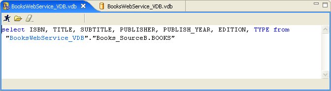
Step 6 - A SELECT statement will appear in the SQL Editor (upper right).
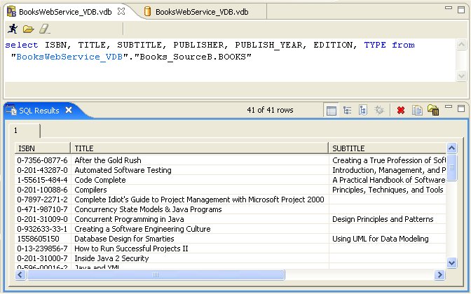
Step 7 - Click the Execute SQL icon
to run the query. The results will appear in the SQL Results tab (lower right).
When executing queries on XML View Documents, the results are displayed in XML format as shown below:

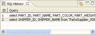
When each query is executed, the SQL is stored in the SQL History table so the queries can be re-submitted without re-typing it.
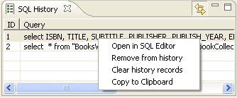
This content of this SQL History table can be edited via right-click menu shown below.
Saving Your Query Results
Query results, both SQL and XML, can be saved to text files in the SQL Explorer perspective.
The toolbars for SQL Results and XML Results views contains an additional action/button (see below) which presents a file save dialog. Note that the action can also be accessed via the right-click menu on both views.

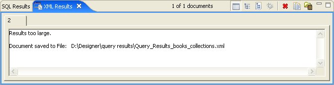
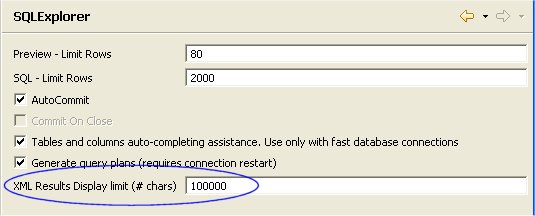
In addition, this file save dialog is presented to the user when the XML Document results exceed the character size limit defined by a user preference property for the SQL Explorer.
When this limit is exceeded, the user is presented with a dialog to either save the results to a file or continue displaying the results and possibly incurring substantial runtime memory allocation.
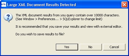
When the Save option is accepted, the XML Query Results view displays the file name and path of the exported file.