While the Portlet 2.0 specification provides for more advanced coordination between portlets than the 1.0 version of the specification, it is left up to specific implementations how portlets are wired together. This chapter will look into how the coordination features are implemented in JBoss Portal.
If you are interested in these features, we strongly encourage you to read the Portlet 2.0 (JSR-286) specification as we will assume in this chapter that you are familiar with the different coordination concepts.
Most JSR-286 specification implementations support the coordination features using what is called an implicit coordination model. This model is called implicit because the relations between the different interacting portlets are inferred based on the event or parameter names that are used to pass information between the portlets. This follows the well-known principle of convention over configuration and provides a good default behavior as it doesn't require explicit user action to wire portlets.
However, such an implicit model of how portlets are wired together fails to handle more complex cases. In particular, it is often the case that semantically related events or public parameters are named differently by different portlet providers. As it is not always possible to modify the portlets to adjust for this minor naming difference of otherwise semantically compatible portlets, JBoss Portal introduces an explicit coordination model that takes precedence over the implicit model when so required.
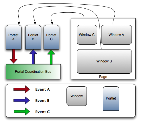
Consider, for example, the following case: we have 3 windows (A, B
and C) on a given page. Each window is associated to a given portlet
(Portlet A, Portlet B and Portlet C, respectively).
Portlet A can produce the Event A event, while
Portlet B and Portlet C can consume Event B and
Event C, respectively. Assuming that these events are semantically equivalent, we would
like to wire these portlets via their events such that when Portlet A emits an
Event A, it gets converted to the appropriate event and transmitted to both
Portlet B and Portlet C so that their respective windows can be
appropriately updated. This scenario, as depicted below, is impossible using implicit
wiring of events:
We look at how to bypass the default implicit model using JBoss Portal's explicit model in the rest of this chapter. It is, however, interesting to note that JBoss Portal can function with both models at the same time. More precisely, it is possible to use the implicit handling of coordination while still specifying explicit wirings, as we will see later.
As most other features of JBoss Portal, the coordination functionality can be configured either declaratively
using the now familiar *-object.xml descriptors (see Chapter 6, XML Descriptors for
a refresher on these descriptors) or, at runtime, using the administration configuration GUI. We detail, below,
both configuration options for each type of coordination entities.
Note
Explicit coordination is currently scoped only at the page level. More specificially, explicit coordination between portlets is only supported between portlets located on the same page.
Launching JBoss Portal's administration interface, you will notice a few changes. In particular, a new option
is available on page configuration screens: the ability to configure coordination using the
Coordination action:
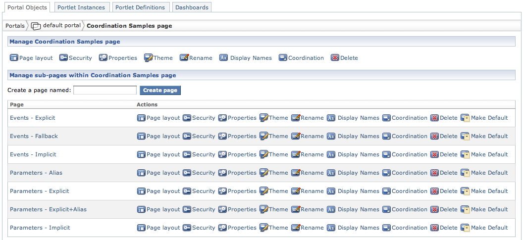
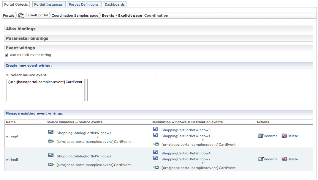
Clicking on that link will bring you to the coordination configuration for that particular page. The interface is organized in three sections, each of which is collapsible by clicking on the section header. These sections detail the configuration for each coordination element that can be controlled by JBoss Portal:
Alias bindings
Parameter bindings
Event wirings
We will look at the specific configuration and what each of these concepts mean later. Here is how the interface looks like for a page, with both the alias and parameter bindings section collapsed:
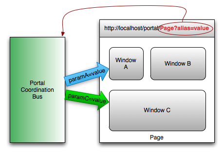
Alias bindings are a JBoss Portal specific feature which allows users to define an
alias to a public render parameter that can be used in URLs to pass a value to all portlet windows reacting
to the aliased public parameter(s). The syntax for the URL is as follows:
{portal URL}/{page name}?{alias name}={alias value}.
It is, for example, possible to alias public render parameters paramA and
paramC to the "alias" name so that JBoss Portal's event bus can
transmit that value to interested portlets on a given page when the requested page URL contains a value
for the appropriate URL parameter:
Explicit alias bindings can be defined in any page definition of your *-object.xml
descriptors. For example, this is how the example that we detailed above would be implemented, within a
page definition:
... <coordination><bindings>
<implici
t-mode>FALSE</implicit-mode> <alias-b
inding> <id>alias</id> <qname>paramA</qname> <qname>paramC</qname> </alias-binding> </bindings> </coordination>
|
Coordination configuration is done via the newly introduced |
|
Alias bindings are defined using the |
|
We specify here that we want JBoss Portal to send parameter values when an explicit bindings are
defined ( |
| An alias binding definition consists of:
In this example, we defined an alias binding named " |
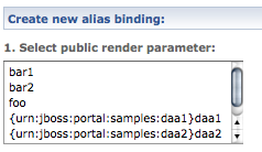
Creating a new alias binding is done by first selecting one or more public parameters that will be used for the binding:
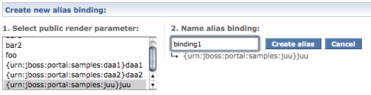
The interface will prompt you for a name for this new binding:
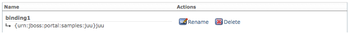
Clicking on Create alias will create the new binding and it will appear in the existing binding lists:
A parameter binding allows users to specify that public render parameters with different names are semantically equivalent so that when one such parameter is updated, all the portlets that can handle such a parameter receive the update, regardless of the name of the parameter that got updated. In the implicit case, portlets can only react to changes of values in parameters whose name they know.
Consider the following example. We are deploying two portlets, Portlet A and
Portlet B, from different vendors and assign them to
Window A and Window B, respectively. Each portlet can react to a
specific public render parameter ({nsA}paramA and {nsB}paramB,
respectively). Under the implicit coordination model, these portlets wouldn't be able
to communicate even if both parameters were semantically equivalent. JBoss Portal's explicit coordination
model allows users to explicit the semantic link between both parameter names such that, when
Portlet A updates the value of {nsA}paramA, Portlet B
gets notified of the update via a change of value of {nsB}paramB:

Explicit parameter bindings can be defined in any page definition of your *-object.xml
descriptors. For example, this is how the example that we detailed above would be implemented, within a
page definition:
... <coordination>
|
Coordination configuration is done via the newly introduced |
|
Parameter bindings are defined using the |
| A parameter binding definition consists of:
In this example, we defined a parameter binding named " |
| A window / parameter name pair identifying either a public parameter to be wired. |
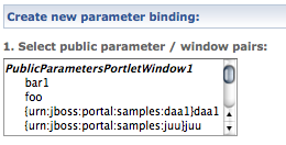
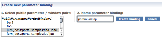
Creating a new parameter binding is done by first selecting a public parameter / window from the list:
The interface will prompt you for a name for this new binding:
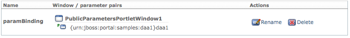
Clicking on Create binding will create the new binding and it will appear in the existing binding lists:
An event wiring wires an event produced by specified portlet windows to consumer portlet windows. In the implicit form, this wiring associates producer and consumer via the event's qualified name (QName).
Explicit event wirings can be defined in any page definition of your *-object.xml
descriptors. For example, this is how the example that we detailed above would be implemented, within a
page definition:
... <coordination>>wiring</name> <sour
ces> <
window-coordination> <window-name>Window A</window-name> <qname>Event A</qname> </window-coordination> </sources> <dest
inations> <window-coordination> <window-name>Window B</window-name> <qname>Event B</qname> </window-coordination> <window-coordination> <window-name>Window C</window-name> <qname>Event C</qname> </window-coordination> </destinations> </event-wiring> </wirings> </coordination>
|
Coordination configuration is done via the newly introduced |
|
Event wirings are defined using the |
| We specify here that we default to implicit wiring of events for this page. However, we will define one explicit event wiring that will take precedence over the implicit wiring when needed. |
| An event wiring definition consists of:
|
| The name of the event wiring which must be unique in the scope of the specified page. |
|
The list of source events, each being identified by a
|
| A window / event name pair identifying either a source or destination of event to be mapped. |
|
The list of destination events, each being identified by a
|
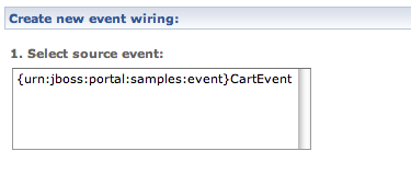
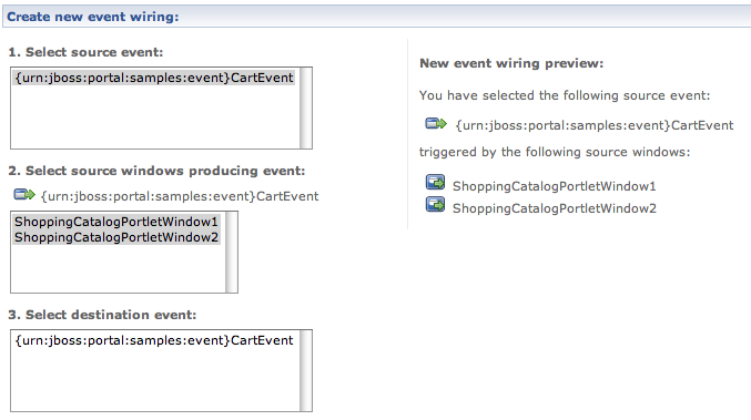
Creating a new event wiring is fairly easy as the interface will guide you. First, it will present a list of available produced events on this page:
Select an event. The interface will display the list of all windows producing this event for this page. Note
also that your selection is summarized on the right side of the screen:
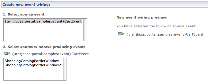
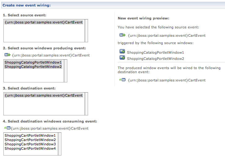
Selecting one or more windows (here we selected two) will continue the process. The interface will now
present you with the list of consumed events on this page, while your new event wiring is still be being
built up on the right side of the screen:
Select a destination event and be presented with the list of windows consuming that event:
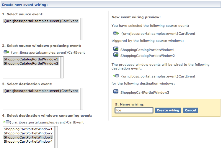
Select one or more destination windows to which the source event will be mapped via the destination event.
You will now be ask to name your new event wiring after having the opportunity to review what will be
created. We name our new event wiring foo here:
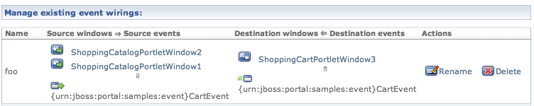
Click on the Create wiring button. Your new event wiring has been created and will appear
in the list of existing wirings:
While the new <coordination> element can be used in both
<page> and <portal> elements, the only configuration that
can be specified at the portal level is whether to use the implicit mode or not:
<portal>

      ...

      <coordination>

         <bindings>

            <implicit-mode>TRUE</implicit-mode>

         </bindings>

         <wirings>

            <implicit-mode>FALSE</implicit-mode>

         </wirings>

      </coordination>

      ...

</portal>
Specifying this <implicit-mode> element at the portal level allows the user to specify
which default behavior to apply to child pages. Quite reasonably, if <implicit-mode>
is set to TRUE then the implicit mode will be used by default. This does not, however,
preclude specific pages to define explicit associations where needed. Setting
<implicit-mode> to FALSE, however, completely deactivates the
implicit handling of coordination features, leaving it up to users to configure only the associations that
need to be made. Note also that the implicit mode can be set for either bindings or
wirings. If no value is provided, implicit mode is used by default.
As part of the core-samples module, JBoss Portal provides several examples of how
coordination can be used. These examples are gathered in the Coordination Samples page. You
can look at how the examples are configured using the administration interface or by looking at the
portal-coordination-samples.war/WEB-INF/default-object.xml file.