Editors are the UI components designed to assist editing your models and to maintain the state for a given model or resource in your workspace. When editing a model, the model will be opened in a Model Editor. Editing a property value, for instance, will require an open editor prior to actually changing the property.
Any number of editors can be open at once, but only one can be active at a time. The main menu bar and toolbar for Teiid Designer may contain operations that are applicable to the active editor (and removed when editor becomes inactive).
Tabs in the editor area indicate the names of models that are currently open for editing. An asterisk (*) indicates that an editor has unsaved changes.
By default, editors are stacked in the editors area, but you can choose to tile them vertically, and or horizontally in order to view multiple models simultaneously.

The Teiid Designer provides main editor views for XMI models and VDBs.
The Model Editor contains sub-editors which provide different views of the data or parts of data within an XMI model. These sub-editors, specific to model types are listed below.
Diagram Editor - All models except XML Schema models.
Table Editor - All models.
Simple Datatypes Editor - XML Schema models only.
Semantics Editor - XML Schema models only.
Source Editor - XML Schema models only.
The VDB Editor is a single page editor containing panels for editing description, model contents and data roles.
In addition to general Editors for models, there are detailed editors designed for editing specific model object types. These "object" editors include:
Transformation Editor - Manages Transformation SQL for Relational View Base Tables, Procedures and XML Service View Operations.
Choice Editor - Manages properties and criteria for XML choice elements in XML Document View models.
Input Editor - Manages Input Set parameters used between Mapping Classes in XML Document View models.
Recursion Editor - Manages recursion properties for recursive XML Elements in XML Document View models.
Operation Editor - Manages SQL and Input Variables for Web Service Operations.
The Model Editor is comprised of sub-editors which provide multiple views of your data. The Diagram Editor provides a graphical while the Table Editor provides spreadsheet-like editing capabilities. This section describes these various sub-editors.
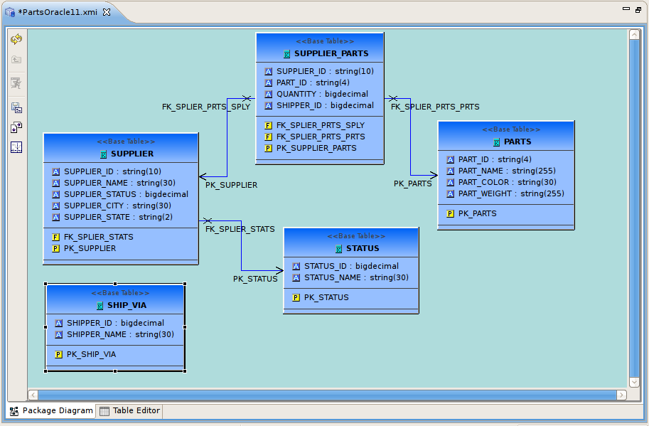
The Diagram Editor provides a graphical view of the a set of model components and their relationships.
Several types of diagrams are available depending on model type. They include:
 Package Diagram
 Custom Diagram
 Transformation Diagram
 Mapping Diagram
- Mapping Transformation Diagram
 Relationship Diagram
You can customize various diagram visual properties via Diagram Preferences.
Each diagram provides actions via the Main toolbar, diagram toolbar and selection-based context menus. These actions will be discussed below in detail for each diagram type.
When a Diagram Editor is in focus, a set of common diagram actions is added to the application's main toolbar.
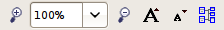
The actions include:
 Zoom In
 Zoom to Level
 Zoom Out
 Increase Font Size
 Decrease Font Size
 Perform Diagram Layout
The Package Diagram provides a graphical view of the contents of a model container, be it the model itself, a relational catalog or schema.
Package Diagram toolbar actions include:
 Refresh Diagram - Re-draws diagram.
 Show Parent Diagram - Navigates to diagram for parent object (if available).
 Preview Data - Executes a simple preview query (SELECT * FROM ).
 Save Diagram as Image - Save the diagram image to file in JPG or BMP format.
 Modify Diagram Printing Preferences - Modify page layout information for printing diagrams. Includes margins, orientation, etc...

 Show/Hide Page Grid - Show current page boundaries as grid in diagram.
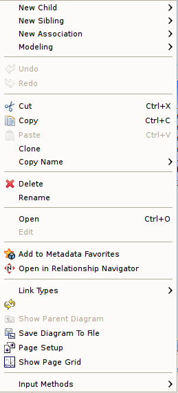
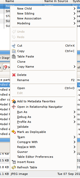
Context menus provide a flexible means to edit model data, especially from Package Diagrams. Each Package Diagram represents the contents of some container (i.e. Model, Category, Schema, etc...), so New Child, New Sibling and New Association actions are almost always available in addition to standard Edit actions (Delete, Cut, Copy, Paste, Rename, Clone).
A sample context menu for a relational base table is shown below.
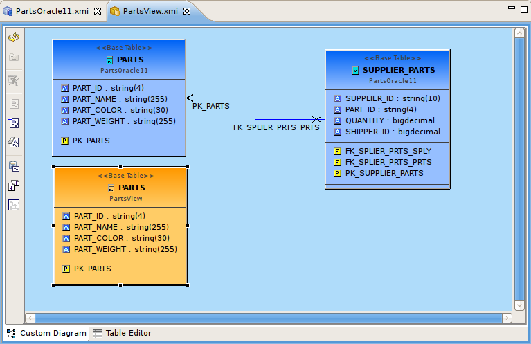
The Custom Diagram represents a view of user-defined model objects. Unlike Package Diagrams, Custom Diagrams can contain objects that are not only unrelated, but can be from different containers and even models.
Custom Diagram toolbar actions include:
- Refresh Diagram - Re-draws diagram.
- Show Parent Diagram - Navigates to diagram for parent object (if available).
- Preview Data - Executes a simple preview query (SELECT * FROM ).
 Add To Diagram - Add objects selected in Model Explorer to diagram.
 Remove From Diagram - Removed objects selected in diagram from diagram.
 Clear Diagram - Remove all objects from diagram.
- Save Diagram as Image - Save the diagram image to file in JPG or BMP format.
- Modify Diagram Printing Preferences - Modify page layout information for printing diagrams. Includes margins, orientation, etc...
- Show/Hide Page Grid - Show current page boundaries as grid in diagram.
Since Custom Diagrams do not represent represents the contents of container objects(i.e. Model, Category, Schema, etc...) its context menus are limited to adding/removing objects from diagram and basic diagram-related display options.
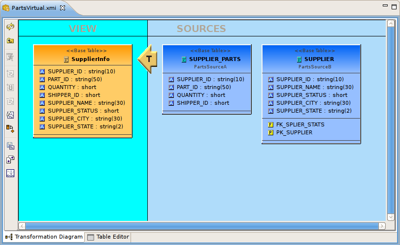
The Transformation Diagram represents a view of the relationships defined by the source inputs described in a view table's SQL transformation.
Transformation Diagram toolbar actions include:
- Refresh Diagram - Re-draws diagram.
- Show Parent Diagram - Navigates to diagram for parent object (if available).
- Preview Data - Executes a simple preview query (SELECT * FROM ).
- Add Transformation Sources - Add selected sources to transformation.
 Add Union Transformation Sources - Add selected sources as union sources.
- Remove Transformation Sources - Removed sources selected in diagram from transformation.
- Clear Transformation - Remove all sources from transformation.
 Open Transformation Reconciler dialog
- Save Diagram as Image - Save the diagram image to file in JPG or BMP format.
- Modify Diagram Printing Preferences - Modify page layout information for printing diagrams. Includes margins, orientation, etc...
- Show/Hide Page Grid - Show current page boundaries as grid in diagram.
Context menus for the
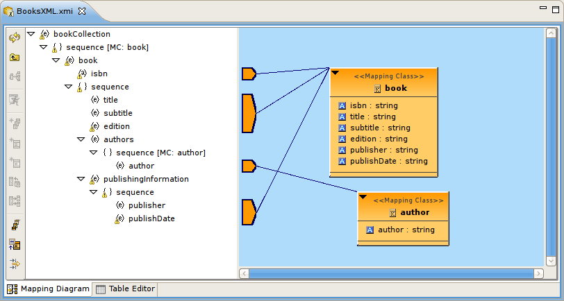
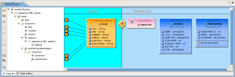
The Mapping Diagram represents a view of the mapping between virtual mapping class columns and XML document elements. This mapping defines how source data is transformed from row-based results into XML formatted text.
Mapping Diagram toolbar actions include:
- Refresh Diagram - Re-draws diagram.
- Show Parent Diagram - Navigates to diagram for parent object (if available).
 Show Mapping Transformation Diagram - Show detailed mapping transformation diagram for selected mapping class.
- Preview Data - Executes a simple preview query (SELECT * FROM ).
 Generate Mapping Classes - Generate mapping classes for the selected XML document root element.
 New Mapping Class - Insert new mapping class referenced to the selected XML document element or attribute..
 New Staging Table - Insert new staging table referenced to the selected XML document element or attribute.
 Merge Mapping Classes - Merge selected mapping classes.
 Split Mapping Class - Split selected mapping class.
 Display All Mapping Classes
 Show Mapping Class Columns
 Filter Displayed Mapping Classes with Selection
Context menus for Mapping Diagrams provide Edit capability to the mapping class in addition to mapping class manipulation actions (i.e. Merge Mapping Classes, Split Mapping Class, etc..)
The Mapping Transformation Diagram is identical to a Transformation Diagram except for displaying an Input Set and possibly Staging Tables as sources for the Mapping Class's transformation.
Mapping Transformation Diagram toolbar actions include:
- Refresh Diagram - Re-draws diagram.
- Show Parent Diagram - Navigates to diagram for parent object (if available).
- Preview Data - Executes a simple preview query (SELECT * FROM ).
 New Mapping Link - Create a mapping link between selected mapping extent (i.e. XML element or attribute) and mapping class column.
 Remove Mapping Link - Delete mapping link between selected mapping extent (i.e. XML element or attribute) and mapping class column.
- Add Transformation Sources - Add selected sources to transformation.
- Add Union Transformation Sources - Add selected sources as union sources.
- Remove Transformation Sources - Removed sources selected in diagram from transformation.
- Clear Transformation - Remove all sources from transformation.
- Open Transformation Reconciler dialog
- Save Diagram as Image - Save the diagram image to file in JPG or BMP format.
- Modify Diagram Printing Preferences - Modify page layout information for printing diagrams. Includes margins, orientation, etc...
Context menus for Mapping Transformation Diagrams identical capabilities to the Transformation Diagram with the addition of managing and editing Input Sets.
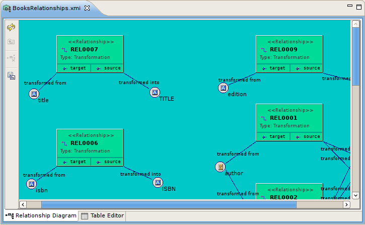
The Relationship Diagram represents a view of relationships between sources and targets defined in your Relationship models as well as the relationships and hierarchy between relationship types.
Relationship Diagram toolbar actions include:
- Refresh Diagram - Re-draws diagram.
- Show Parent Diagram - Navigates to diagram for parent object (if available).
 Remove From Relationship - Removes the selected source or targets from a relationship.
- Save Diagram as Image - Save the diagram image to file in JPG or BMP format.
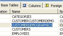
The Table Editor provides a table-based object type structured view of the contents of a model. The figure below shows a relational model viewed in the Table Editor. Common object types are displayed in individual folders/tables. All base tables, for instance, are shown in one table independent of their parentage.
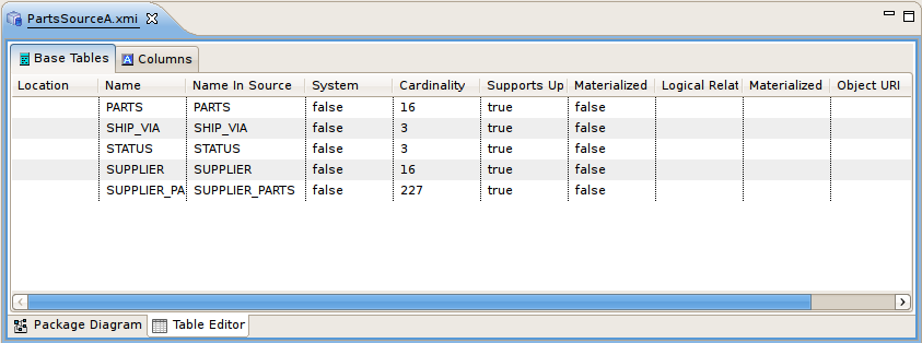
You can customize Table Editor properties via Table Editor Preferences.
These are the primary features of the Table Editor:
Edit existing properties.
Add, remove or edit objects, via the main Edit menu and context menu ( Cut, Copy, Paste, Clone, Delete, Rename, Insert Rows ).
Paste information from your clipboard into the table.
Print your tables.
When a
Table Editor
is in focus, the
Insert Table Rows action ![]() is added to the application's main toolbar.
is added to the application's main toolbar.
A few Table Editor actions are contributed to the right-click menu for selected table rows. These actions, described and shown below include:
 Table Paste - Paste common spreadsheet data (like Microsoft Excel) to set object properties.
Table Editor Preferences - Change table editor preferences, including customizing visible properties.
Insert Rows - Create multiple new sibling objects.
 Refresh Table - Refreshes the contents of the current Table Editor to insure it is in sync with the model.
You can edit properties for an object by double-clicking a table cell.
For String properties, the table cell will become an in-place text editor field.
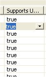
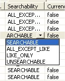
If a property is of a boolean (true or false) type or has multiple, selectable values, a combo box will be displayed to change the value.
For multi-valued properties where the available values are dynamic (i.e. can change based on available models or data), a picker-button ("....") will be displayed.
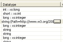
An example of of this type is the relational column datatype property. Editing via the table cell and clicking the "..." button for datatype will display the following dialog.
The Insert Rows action provides an additional way to create objects in a model. Insert Rows action performs the same function as Insert Sibling action, but allows you to create multiple children at the same time. All new rows will correspond to an object of the same type as the selected object and be located under the same parent as the selected object.
To Insert Rows in a table:
Step 1: Select a table row to insert rows after.
Step 2: Right-click select "Insert Rows" action or select the Insert Rows action on the main toolbar. The following dialog will be displayed.
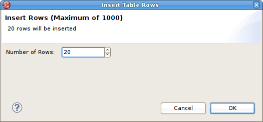
Step 3: Edit the Number of Rows value in the dialog, or use the up/down buttons to change the value.
Step 4: Select OK in dialog.
The desired number of rows (new model objects) will be added after the original selected table row.
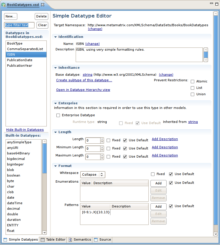
The Simple Datatype Editor provides a form-based properties view of XML Schema data.
The Semantic Editor is a tree based editor for XML Schema elements and attributes.
The Source Editor is a simple text editor which is aware of XML Schema formatting rules.
The Model Object Editors represent specialized sub-editors which are available for specific model object types.
For details, select a specific editor listed below:
A VDB, or virtual database is a container for components used to integrate data from multiple data sources, so that they can be accessed in a federated manner through a single, uniform API. A VDB contains models, which define the structural characteristics of data sources, views, and Web services. The VDB Editor, provides the means to manage the contents of the VDB as well as its deployable (validation) state.
The VDB Editor, shown below, contains a Description area, a Models area, an Other Files panel and a VDB Data Roles panel.
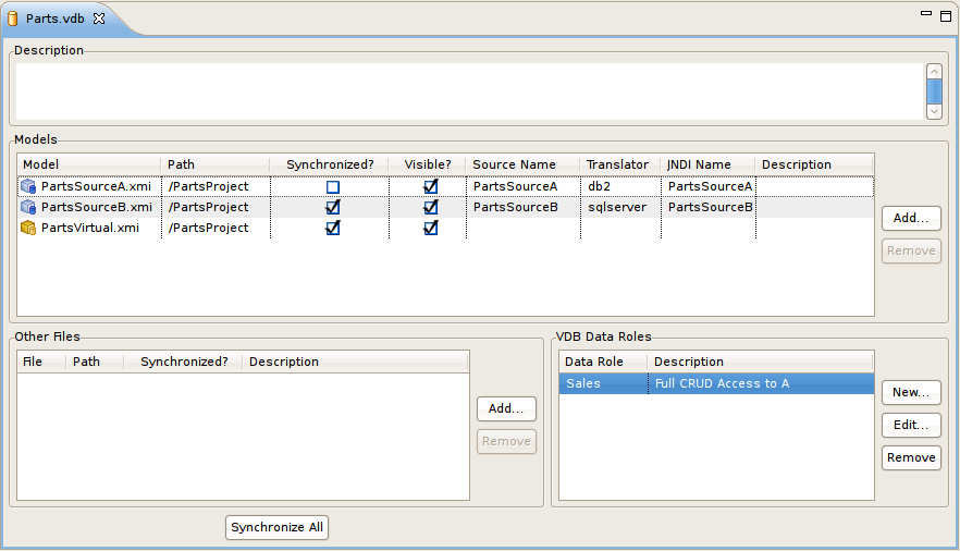
You can manage your VDB contents by using the Add or Remove models via the buttons at the right.
Set individual model visibility via the Visibility checkbox for each model. This provides low level data access security by removing specific models and their metadata contents from schema exposed in GUI tools.
In order for a VDB to be fully queryable the "Source Name", "Translator" and "JNDI Names" must have valid values and represent deployed artifacts on your Teiid server.
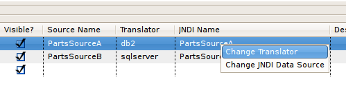
If you have Designer runtime plugins installed, and have a Teiid server running, you can select a source model in the VDB Editor and right-click select "Change Translator" or "Change JNDI Data Source" which will allow you to select any applicable artifacts on your server.
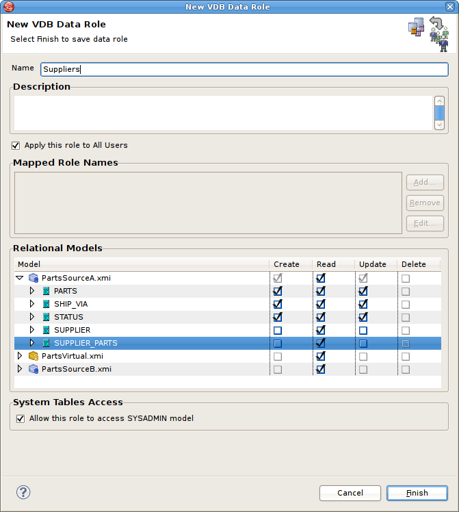
Teiid Designer provides a means to create, edit and manage data roles specific to a VDB. Once deployed within a Teiid server with the security option turned on (by default) any query run against this VDB via a Teiid JDBC connection will adhere to the data access permissions defined by the VDB's data roles.
The VDB Editor contains a VDB Data Roles section consisting of a List of current data roles and New... , Edit... and Remove action buttons.
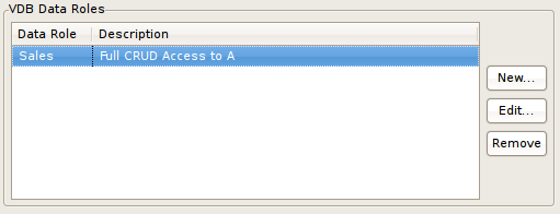
Clicking New... or Edit... will launch the New VDB Data Role editor dialog. Speicify a unique data role name, add a optional description and modify the individual model element CRUD values by check or unchecking entries in the models section.