Create new JBoss Tools Documentation Jira issue

JBoss.orgCommunity Documentation
3.2.0.Beta
Copyright © 2010 Red Hat, Inc.
- 1. Introduction
- 2. Teiid Designer Perspectives
- 3. Teiid Designer Main Menu
- 4. Teiid Designer Views
- 4.1. Model Explorer View
- 4.2. Outline View
- 4.3. UDFs View
- 4.4. Connectors View
- 4.5. Properties View
- 4.6. Description View
- 4.7. Editors
- 4.8. Problems View
- 4.9. Message Log View
- 4.10. Preview Results View
- 4.11. Search Results View
- 4.12. Datatype Hierarchy View
- 4.13. Model Classes View
- 4.14. System Catalog View
- 4.15. Database Structure View
- 4.16. SQL History View
- 4.17. Connections View
- 4.18. SQL Editor View
- 4.19. SQL Results View
- 5. Editors
- 6. Importers
- 7. New Model Wizards
- 7.1. Creating New Relational Source Model
- 7.2. Creating New Relational View Model
- 7.3. Creating New XML Service Source Model
- 7.4. Creating New XML Service View Model
- 7.5. Creating XML Document View Model
- 7.6. Creating XML Schema Model
- 7.7. Creating Web Service View Model
- 7.8. Creating New Extensions Model
- 7.9. Creating New Relationship Model
- 7.10. Creating New UML 2.0 Model
- 8. Creating and Editing Model Objects
- 9. Editing Models and Projects
- 10. Testing Your Models
- 11. Searching
- 12. Relationships
- 13. User Preferences
Go To: Table of Contents
The Teiid Designer User's Guide provides detailed descriptions of Teiid Designer features and functionality.
Teiid Designer is an Eclipse-based graphical modeling tool for modeling, analyzing, integrating and testing multiple data sources to produce Relational, XML and Web Service Views that expose your business data.
Teiid Designer is a visual tool that enables rapid, model-driven definition, integration and testing of data services without programming. With Teiid Designer , not only do you map from data sources to target formats using a visual tool, but you can also:
resolve semantic differences
create virtual data structures at a physical or logical level
use declarative interfaces to integrate, aggregate, and transform the data on its way from source to a target format which is compatible and optimized for consumption by your applications
resolve semantic differences
This allows you to abstract the structure of the information you expose to and use in your applications from the underlying physical data structures. With Teiid Designer, data services are defined quickly, the resulting artifacts are easy to maintain and reuse, and all the valuable work and related metadata are saved for later reference.
You can use Teiid Designer to integrate multiple sources, and access them using the common data access standards:
Web Services / SOAP / XML
JDBC / SQL
ODBC / SQ
Teiid Designer is an integral part of the Teiid Designer enterprise-class system for providing data services for service-oriented architectures.
Metadata is data about data. A piece of metadata, called a meta object in the Teiid Designer, contains information about a specific information structure, irrespective of whatever individual data fields that may comprise that structure.
Let’s use the example of a very basic database, an address book. Within your address book you certainly have a field or column for the ZIP code (or postal code number). Assuming that the address book services addresses within the United States, you can surmise the following about the column or field for the ZIP code:
Named ZIPCode
Numeric
A string
Nine characters long
Located in the StreetAddress table
Comprised of two parts: The first five digits represent the five ZIP code numbers, the final four represent the ZIP Plus Four digits if available, or 0000 if not
Formatted only in integer numeric characters. Errors will result if formatted as 631410.00 or 6314q0000
This definition represents metadata about the ZIP code data in the address book database. It abstracts information from the database itself and becomes useful to describe the content of your enterprise information systems and to determine how a column in one enterprise information source relates to another, and how those two columns could be used together for a new purpose
You can think of this metadata in several contexts:
What information does the metadata contain? (see Business and Technical Metadata)
What data does the metadata represent? (see Source and View Metadata)
How will my organization use and manage this metadata? (see Design-Time and Runtime Metadata)
The Teiid Designer helps you to create and describe an abstract graphic representation of your data structure of your data in the original data sources. It also describes whether those data sources are composed of Relational databases, text files, data streams, legacy database systems, or some other information type.
The Teiid Designer allows you to create, edit, and link these graphically-represented meta objects that are really a description of your data, and not the data itself.
So when this documentation describes the process of creating, deleting, or editing these meta objects, remember that you are not, in fact, modifying the underlying data.
A metadata model represents a collection of metadata information that describes a complete structure of data.
In a previous example we described the field ZIPCode as a metadata object in an address book database.. This meta object represents a single distinct bit of metadata information. We alluded to its parent table, StreetAddress. These meta objects, and others that would describe the other tables and columns within the database, would all combine to form a Source Metadata model for whichever enterprise information system hosts all the objects.
You can have Source Models within your collection of metadata models These model physical data storage locations. You can also have View Models, which model the business view of the data. Each contains one type of metadata or another. For more information about difference between Source and View metadata, see “Source and View Metadata.”
NOTE: For detailed information about creating models from your metadata, see Models 101
Metadata can include different types of information about a piece of data.
Technical metadata describes the information required to access the data, such as where the data resides or the structure of the data in its native environment.
Business metadata details other information about the data, such as keywords related to the meta object or notes about the meta object.
Note that the terms technical and business metadata, refer to the content of the metadata, namely what type of information is contained in the metadata. Don’t confuse these with the terms “physical” and “view” metadata that indicate what the metadata represents. For more information, see Source and View Metadata.
Technical metadata represents information that describes how to access the data in its original native data storage. Technical metadata includes things such as datatype, the name of the data in the enterprise information system, and other information that describes the way the native enterprise information system identifies the meta object
Using our example of an address book database, the following represent the technical metadata we know about the ZIP code column:
Named ZIPCode
Nine characters long
A string
Located in the StreetAddress table
Uses SQL Query Language
These bits of information describe the data and information required to access and process the data in the enterprise information system.
Business metadata represents additional information about a piece of data, not necessarily related to its physical storage in the enterprise information system or data access requirements. It can also represent descriptions, business rules, and other additional information about a piece of data.
Continuing with our example of the ZIP Code column in the address book database, the following represents business metadata we may know about the ZIP code:
The first five characters represent the five ZIP code numbers, the final four represent the ZIP Plus Four digits if available, or 0000 if not
The application used to populate this field in the database strictly enforces the integrity of the data format
Although the first might seem technical, it does not directly relate to the physical storage of the data. It represents a business rule applied to the contents of the column, not the contents themselves.
The second, of course, represents some business information about the way the column was populated. This information, although useful to associate with our definition of the column, does not reflect the physical storage of the data.
Teiid Designer software distinguishes between design-time metadata and run-time metadata. This distinction becomes important if you use the Teiid Designer Server. Design-time data is laden with details and representations that help the user understand and efficiently organize metadata. Much of that detail is unnecessary to the underlying system that runs the Virtual Database that you will create. Any information that is not absolutely necessary to running the Virtual Database is stripped out of the run-time metadata to ensure maximum system performance.
Design-time metadata refers to data within your local directory that you have created or have imported. You can model this metadata in the Teiid Designer, adding Source and View metadata.
Once you have adequately modeled your enterprise information systems, including the necessary technical metadata that describes the physical structure of your sources, you can use the metadata for data access.
To prepare the metadata for use in the Teiid Designer Server, you take a snapshot of a metadata model for the Teiid Designer Server to use when resolving queries from your client applications. This run-time metadata represents a static version of design-time metadata you created or imported. This snapshot is in the form of a Virtual Database definition, or VDB.
As you create this runtime metadata, the Teiid Designer:
derives the runtime metadata from a consistent set of metadata models.
creates a subset of design-time metadata, focusing on the technical metadata that describes the access to underlying enterprise information systems.
optimizes runtime metadata for data access performance.
You can continue to work with the design-time metadata, but once you have created a runtime metadata model, it remains static.
In addition to the distinction between business and technical metadata, you should know the difference between Source Metadata and View Metadata.
Source and View metadata refer to what the metadata represents, not its content.
Source Metadata directly represents metadata for an enterprise information system and captures exactly where and how the data is maintained. Source Metadata sounds similar to technical metadata, but Source Metadata can contain both technical and business metadata. When you model Source Metadata, you are modeling the data that your enterprise information systems contain. For more information, see “Modeling Your Teiid Designer Information Systems.”
View Metadata, on the other hand, represent tailored views that transform the Source Metadata into the terminology and domain of different applications. View Metadata, too, can contain both technical and business metadata. When you model View Metadata, you’re modeling the data as your applications (and your enterprise) ultimately use it. For more information, see “Modeling Your Teiid Designer Data Needs.”
When you model the Source Metadata within your enterprise information systems, you capture some detailed information, including:
Identification of datatype
Storage formats
Constraints
Source-specific locations and names
The Source Metadata captures this detailed technical metadata to provide a map of the data, the location of the data, and how you access it.
This collection of Source Metadata comprises a direct mapping of the information sources within your enterprise. If you use the Teiid Designer Server for information integration, this technical metadata plays an integral part in query resolution.
For example, our ZIPCode column and its parent table StreetAddress map directly to fields within our hypothetical address book database.
To extend our example, we might have a second source of information, a comma-separated text file provided by a marketing research vendor. This text file can supply additional demographic information based upon address or ZIP code. This text file would represent another EIS, and the meta objects in its Source Model would describe each comma-separated value.
When you create View Metadata, you are not describing the nature of your physical data storage. Instead, you describe the way your enterprise uses the information in its day-to-day operations.
View Metadata derives its classes and attributes from other metadata. You can derive View Metadata from Source Metadata that describes the ultimate sources for the metadata or even from other View Metadata. However, when you model View Metadata, you create special “views” on your existing enterprise information systems that you can tailor to your business use or application expectations. This View Metadata offers many benefits:
You can expose only the information relevant to an application. The application uses this View Metadata to resolve its queries to the ultimate physical data storage.
You can add content to existing applications that require different views of the data by adding the View Metadata to the existing View Metadata that application uses. You save time and effort since you do not have to create new models nor modify your existing applications.
Your applications do not need to refer to specific physical enterprise information systems, offering flexibility and interchangeability. As you change sources for information, you do not have to change your end applications.
The View Metadata models document the various ways your enterprise uses the information and the different terminology that refers to that information. They do so in a central location.
Our example enterprise information sources, the address book database, and the vendor-supplied comma-delimited text file, reside in two different native storage formats and therefore have two Source Metadata models. However, they can represent one business need: a pool of addresses for a mass mailing.
By creating a View Metadata model, we could accurately show that this single View Table, the AddressPool, contains information from the two enterprise information systems. The View Metadata model not only shows from where it gets the information, but also the SQL operations it performs to select its information from its source models.
This View Metadata can not only reflect and describe how your organization uses that information, but, if your enterprise uses the Teiid Designer Server, your applications can use the View Metadata to resolve queries.
To create this View Metadata, you create a view and define a transformation for that view, a special query that enables you to select information from the source (or even other view) metadata models. For more information, see “Transformation Editor.”
Section on Modeling transformations.
By modeling View Metadata, you can illustrate the business view of your enterprise information sources. View Metadata models not only describe that business view, but also illustrate how the meta objects within the View Metadata models derive their information from other metadata models.
Let’s return to the example of our address book database and the vendor’s comma-separated list. We want to generate the View Metadata model, Address Pool, from these enterprise information systems.
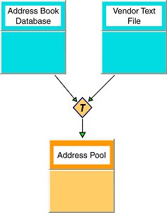
The transformation that joins these metadata models to create the virtual Address Pool metadata model contains a SQL query, called a union, that determines what information to draw from the source metadata and what to do with it.
The resulting Address Pool contains not only the address information from our Address Book database, but also that from our vendor-supplied text file.
Transformations contain SQL queries that SELECT the appropriate attributes from the information sources.
For example, from the sources the transformation could select relevant address columns, including first name, last name, street address, city, state, and ZIP code. Although the metadata models could contain other columns and tables, such as phone number, fax number, e-mail address, and Web URL, the transformation acts as a filter and populates the Address Pool metadata model with only the data essential to building our Address Pool.
You can add other SQL logic to the transformation query to transform the data information. For example, the address book database uses a nine-character string that represents the ZIP Plus Four. The transformation could perform any SQL-supported logic upon the ZIPCode column to substring this information into the format we want for the Address Pool View metadata model.
When you model View Metadata, you can also create a View XML Document model. This View Document lets you select information from within your other data sources, just like a regular View Metadata model, but you can also map the results to tags within an XML document.
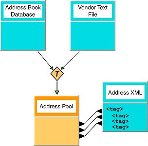
In this example, the Address Pool View Metadata model still selects its information from the Address Book Database and the Vendor Text File, but it also maps the resulting columns into tags in the Address XML document.
A model is a representation of a set of information constructs. A familiar model is the relational model, which defines tables composed of columns and containing records of data. Another familiar model is the XML model, which defines hierarchical data sets.
In Teiid Designer, models are used to define the entities, and relationships between those entities, required to fully define the integration of information sets so that they may be accessed in a uniform manner, using a single API and access protocol. The file extension used for these models is '.xmi' ( Example: NorthwindOracle.xmi ) which adheres to the XMI syntax defined by the OMG.
Below is an example of the partial contents of a model file.
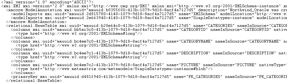
Model files should never be modified "by hand". While it is possible to do so, there is the possibility that you may corrupt the file such that it cannot be used within the Teiid Designer system.
The fundamental models in Teiid Designer define the structural and
data characteristics of the information contained in data sources.
These are referred to as source models (represented by ![]() ). Teiid Designer
uses the information in source models to federate the information in
multiple sources, so that from a user's viewpoint these all appear to
be in a single source.
). Teiid Designer
uses the information in source models to federate the information in
multiple sources, so that from a user's viewpoint these all appear to
be in a single source.
In addition to source models, Teiid Designer provides the ability to
define a variety of view models(represented by ![]() ). These can be used to
define a layer of abstraction above the physical (or source) layer, so
that information can be presented to end users and consuming
applications in business terms rather than as it is physically stored.
Views are mapped to sources using transformations between models.
These business views can be in a variety of forms:
). These can be used to
define a layer of abstraction above the physical (or source) layer, so
that information can be presented to end users and consuming
applications in business terms rather than as it is physically stored.
Views are mapped to sources using transformations between models.
These business views can be in a variety of forms:
Relational Tables and Views
XML
XML Service
Web services
Relationships
Functions
UML 2.0
A third model type, logical, provides the ability to define models from a logical or structural perspective.
Models are defined using Teiid Designer in various ways:
Created via importing source data characteristics. (see Import Wizard)
Manual creation via New Model Wizard
Transforming or copying from one model into another (see New Model Wizard options)
Various custom actions
Teiid Designer can be used to model a variety of classes of models. Each of these represent a conceptually different classification of models.
Relational - Model data that can be represented in table – columns and records – form. Relational models can represent structures found in relational databases, spreadsheets, text files, or simple Web services.
XML - Model that represents the basic structures of XML documents. These can be “backed” by XML Schemas. XML models represent nested structures, including recursive hierarchies.
XML Schema - W3C standard for formally defining the structure and constraints of XML documents, as well as the datatypes defining permissible values in XML documents.
XML Service - TBD.
Web Services - which define Web service interfaces, operations, and operation input and output parameters (in the form of XML Schemas).
Model Extensions - for defining property name/value extensions to other model classes.
Function - The Function metamodel supports the capability to provide user-defined functions, including binary source jars, to use in custom transformation SQL statements. Currently only a single UDF model is supported by Teiid Designer. See UDFs View for details.
Relationship - TBD.
UML 2.0 - TBD.
VDBs contain two primary varieties of model types - source and view. Source models represent the structure and characteristics of physical data sources, whereas view models represent the structure and characteristics of abstract structures you want to expose to your applications.
Models used for data integration are packaged into a virtual database (VDB). The models must be in a complete and consistent state when used for data integration. That is, the VDB must contain all the models and all resources they depend upon. Models contained within a VDB can be imported into the Teiid Designer. In this way, VDBs can be used as a way to exchange a set of related models. (See description in VDB Editor section)
A connector provides the connectivity to the source for the query engine when it is executing queries to that source.
All Source models must have connectors associated with them in a VDB in order to be tested in Teiid Designer or deployed for data access.
It is possible that multiple models may use the same connector, but each model must have a connector.
In Teiid Designer, connector are automatically created "under the hood" when you import from a specific supported data source. You can also create and maintain your own custom connectors. (see Manage Connectors)
Models must be in a valid state in order to be used for data access. Validation of a single model means that it must be in a self-consistent and complete state, meaning that there are no "missing pieces" and no references to non-existent entities. Validation of multiple models checks that all inter-model dependencies are present and resolvable.
Models must always be validated when they are deployed in a VDB for data access purposes.
Enterprise Teiid Designer will automatically validate your models whenever the user Saves ( Note: the "Models > Validate Automatically" option must be checked). When editing models, the editor tabs will display a "*" to indicate that the model has unsaved changes.
Designing and working with data is often much easier when you can see the information you're working with. The Teiid Designer's Preview Data feature makes this possible and allows you to instantly preview the information described by any object, whether it's a physical table or a virtual view. In other words, you can test the views with actual data by simply selecting the table, view, procedure or XML document. The preview functionality leverages an embedded version of the Teiid Designer Server, so you can be sure that the behavior in the Teiid Designer will reliably match when the VDB is deployed to the Server. Previewing information is a fast and easy way to sample the data. Of course, to run more complicated queries like what your application likely uses, simply execute the VDB in the Teiid Designer and type in any query or SQL statement.
After creating your models, you can test them by using the
Preview Data action ![]() . By selecting a desired table object and
executing the action, the results of a simple query will be displayed
in the Preview results view. This action is accessible throughout the
Teiid Designer in various view toolbars and context menus.
. By selecting a desired table object and
executing the action, the results of a simple query will be displayed
in the Preview results view. This action is accessible throughout the
Teiid Designer in various view toolbars and context menus.
There are two requirements for previewing your data: the selected object must be one several previewable model object types and all source models within the model dependency tree must be bound to connectors.
Previewable objects include:
Relational table or view, including tables involving access patterns.
Relational procedure.
Web Service operation.
XML Document staging table.
Note that any virtual table, view or procedure is previewable as long as all "physical" source models are bound via connectors. (See Connectors view and Manage Connectors)
Note
If attempting to preview a relational access patter, a web service operation or a relational procedure with input parameters, a dialog will be presented to request values for required parameters.
Go To: Table of Contents
Teiid Designer utilizes Eclipse's Workbench environment which controls visual layout via perspectives. A perspective defines the initial set and layout of views and editors. Within the application window, each perspective shares the same set of editors. Each perspective provides a set of functionality aimed at accomplishing a specific set of tasks.
Perspectives also control what appears in certain menus and toolbars. They define visible action sets, which you can change to customize a perspective. You can save a perspective that you build in this manner, making your own custom perspective that you can open again later.
Teiid Designer perspectives include:
Teiid Designer - Default perspective providing fundamental model editing and management capability.
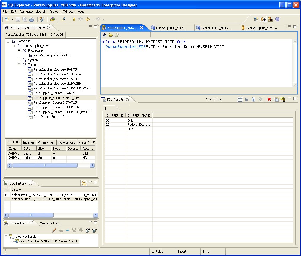
SQL Explorer - Provides views and actions to perform tests on your VDB by connecting to your data sources and executing your test queries.
For more details on perspectives, views and other Eclipse workbench details, see formal Eclipse Documentation.
Opening a Perspective
There are two ways to open a perspective:
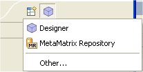
Using the Open Perspective button
 on the shortcut bar.
Choosing a perspective from the Window > Open Perspective menu.
To search for string values in your transformations SQL:
Step 1 - Click on the Open Perspective button
Step 2 - A menu appears showing the same choices as shown on the Window > Open Perspective menu. Choose Other from the menu.
Step 3 - In the Select Perspective dialog choose Teiid Designer and click OK.
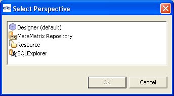
The Teiid Designer perspective is now displayed.
There are few additional features of perspectives to take note of.
The title of the window will indicate which perspective is in use.
The shortcut bar may contain multiple perspectives. The perspective button which is pressed in, indicates that it is the current perspective.
To display the full name of the perspectives, right click the perspective bar and select Show Text and conversely select Hide Text to only show icons.
To quickly switch between open perspectives, select the desired perspective button. Notice that the set of views is different for each of the perspectives.

The Teiid Designer perspective includes several main UI components or groups of components as shown below. They include:
The SQL Explorer perspective includes 4 main UI components or groups of components as shown below. They include:
Go To: Table of Contents
There are 8 categories of actions on Teiid Designer's main menu bar.
These categories include:
File - Resource management actions.
Edit - Standard edit actions including undo/redo.
Refactor - Resource actions (i.e. Rename, Move, etc...).
Search - Find data within your workspace.
Project - Model level actions.
Metadata - Custom metadata-related actions.
Window - Change perspectives or add/remove views to your perspective.
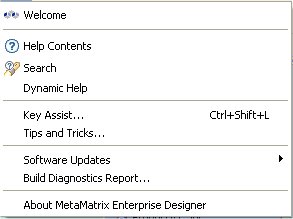
Help - Access available Teiid Designer help documents, Teiid Designer SQL Support Guide and Eclipse Overview information.
The File menu provides actions to manage your workspace resources.
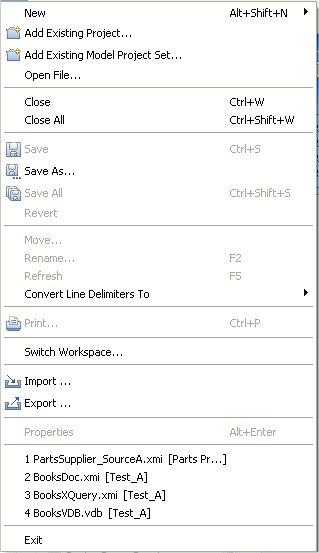
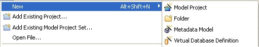
The New > sub-menu provides specific actions to create various generic workspace resources as well as Teiid Designer models and VDBs.
The File menu contains the following actions:
 New > Model Project - Create user a new
model project.
New > Model Project - Create user a new
model project.
 New > Folder - Create new folder
within an existing project or folder.
New > Folder - Create new folder
within an existing project or folder.
 New > Model - Create a new model of
a specified model type and class using
the New Model Wizard.
New > Model - Create a new model of
a specified model type and class using
the New Model Wizard.
 New > Virtual Database Definition - Create a new VDB, or
Virtual Database Definition.
New > Virtual Database Definition - Create a new VDB, or
Virtual Database Definition.
 Add Existing Project... - Add an existing
Teiid Designer project into your workspace.
Add Existing Project... - Add an existing
Teiid Designer project into your workspace.
- Add Existing Model Project Set... - Import
an existing Model Project Set from your file system. A
Model Project Setan be exported via the
Export action.
Open File - Enables you to open a file for editing - including files that do not reside in the Workspace.
Close (Ctrl+W) - Closes the active editor. You are prompted to save changes before the file closes.
Close All (Shift+Ctrl+W) - Closes all open editors. You are prompted to save changes before the files close.
 Save (Ctrl+S) - Saves the contents of
the active editor.
Save (Ctrl+S) - Saves the contents of
the active editor.
 Save As - Enables you to save the
contents of the active editor under another file name or location.
Save As - Enables you to save the
contents of the active editor under another file name or location.
 Save All (Shift+Ctrl+S) - Saves the
contents of all open editors.
Save All (Shift+Ctrl+S) - Saves the
contents of all open editors.
Revert - Replaces the contents of the active editor with the previously saved contents. Currently not implemented for Teiid Designer models or VDBs.
Move… - Launches a Refactor > Move resource dialog..
Rename… (F2) - Launches a Refactor > Rename resource dialog if resource selected, else in-line rename is preformed.
Refresh - Refreshes the resource with the contents in the file system.
Convert Line Delimiters To - Alters the line delimiters for the selected files. Changes are immediate and persist until you change the delimiter again - you do not need to save the file.
 Print (Ctrl+P) - Prints the contents
of the active editor. In the Teiid Designer, this action prints the diagram in the selected editor.
Allows control over orientation (portrait or landscape), scaling,
margins and page order. User can also specify a subset of the pages to
print (i.e., “2 through 8”).
Print (Ctrl+P) - Prints the contents
of the active editor. In the Teiid Designer, this action prints the diagram in the selected editor.
Allows control over orientation (portrait or landscape), scaling,
margins and page order. User can also specify a subset of the pages to
print (i.e., “2 through 8”).
Switch Workspace - Opens the Workspace Launcher, from which you can switch to a different workspace. This restarts the Workbench.
Restart - Exits and restarts the Workbench.
 Import - Launches the
Import Wizard which provides several ways to
construct or import models..
Import - Launches the
Import Wizard which provides several ways to
construct or import models..
 Export - Launches the
Export Wizard which provides options for exporting model data.
Export - Launches the
Export Wizard which provides options for exporting model data.
Properties (Alt+Enter) - Opens the Properties dialog for the currently selected resource. These will include path to the resource on the file system, date of last modification and its writable or executable state.
Most Recent Files List - Contains a list of the most recently accessed files in the Workbench. You can open any of these files from the File menu by simply selecting the file name.
Exit - Closes and exits the Workbench.
The Edit menu provides actions to manage the content, structure and properties of your model and project resources.
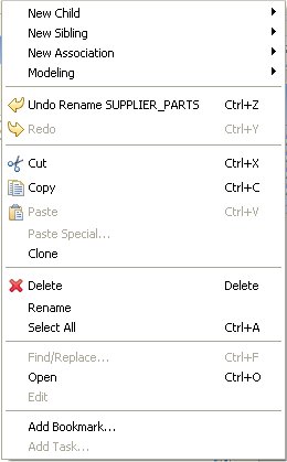
The Edit menu contains the following actions:
New > Child - This menu is created dynamically to support the creation of whatever types of child objects can be created under the selected object.
New > Sibling - This menu is created dynamically to support the creation of whatever types of sibling objects can be created under the same parent as the selected object
New > Association - This menu is created dynamically to support the creation of whatever types of associations can be created with the selected object.
Modeling > - This menu is created dynamically. Various modeling operations are presented based on selected model object type.
 Undo - Reverses the effect of the
most recent command.
Undo - Reverses the effect of the
most recent command.
 Redo - Reapplies the most recently
undone command.
Redo - Reapplies the most recently
undone command.
 Cut - Deletes the selected object(s)
and copies it to the clipboard.
Cut - Deletes the selected object(s)
and copies it to the clipboard.
 Copy - Copies the selected
object(s) to the clipboard.
Copy - Copies the selected
object(s) to the clipboard.
 Paste - Pastes the contents of the
clipboard to the selected context.
Paste - Pastes the contents of the
clipboard to the selected context.
Paste Special... - Provides additional paste capabilities for complex clipboard objects.
Clone - Duplicates the selected object in the same location with the same name. User is able to rename the new object right in the tree.
 Delete - Deletes the selected object(s).
Rename - Allows a user to rename an object in the tree.
Find/Replace - Launches dialog that can be used to search in the current text view, such as a Transformation Editor.
Open - Opens the selected object in the appropriate editor.
Edit - Opens the selected object in the appropriate specialized editor, such as the Choice Editor or Recursion Editor..
Add Bookmark... - This command adds a bookmark in the active file on the line where the cursor is currently displayed.
Add Task... - This command adds a task in the active file on the line where the cursor is currently displayed.
The Refactor menu provides Teiid Designer specific actions for file-level changes to the models.

The Refactor menu contains the following actions:
Undo - Undo the last refactor command.
Redo - Redo the last undone refactor command.
Move - Move a model from one container (folder or project) to another.
Rename - Rename a model.
The Search menu presents several specific search options.
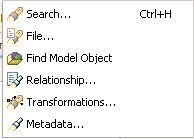
The Search menu contains the following actions:
 Search... - Launches the
standard Search dialog, which can be used to find resource containing specific
text or expressions and filter based on file name patterns. For standard Eclipse
installations, the default search tile will be File Search.
Search... - Launches the
standard Search dialog, which can be used to find resource containing specific
text or expressions and filter based on file name patterns. For standard Eclipse
installations, the default search tile will be File Search.
- File... - Launches the
standard Search dialog, which can be used to find resource containing specific
text or expressions and filter based on file name patterns. The File Search
tab will be selected in the dialog.
 Find Model Object - Launches the
Find Model Object dialog, which can be used to find an object in the
workspace by specifying all or part of its name. Selecting the object
will open it in the appropriate editor.
Find Model Object - Launches the
Find Model Object dialog, which can be used to find an object in the
workspace by specifying all or part of its name. Selecting the object
will open it in the appropriate editor.
 Relationship... - Launches the
Search dialog and auto-selects the Relationships tab. User can search for models in the workspace
by specifying a relationship type, participant locations, and/or names containing sprcified
text. Search results appear in
the Search Results view,
and double-clicking a result will open that model in the appropriate editor.
Relationship... - Launches the
Search dialog and auto-selects the Relationships tab. User can search for models in the workspace
by specifying a relationship type, participant locations, and/or names containing sprcified
text. Search results appear in
the Search Results view,
and double-clicking a result will open that model in the appropriate editor.
 Transformations... - Launches the
Transformation Search dialog. User can search models in
the workspace for matching SQL text. Search results appear in the
dialog and user can select and view SQL as well as open desired transformations for editing.
Transformations... - Launches the
Transformation Search dialog. User can search models in
the workspace for matching SQL text. Search results appear in the
dialog and user can select and view SQL as well as open desired transformations for editing.
- Metadata... - Launches the
Search dialog. User can search for models in the workspace by
specifying an Object Type, and/or a Data Type, and/or a property value.
Search results appear in
the Search Results view,
and double-clicking a result will open that model in the appropriate editor.
The Project Menu menu ...
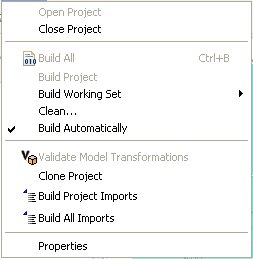
The Project menu contains the following actions:
Open Project - Launches the Open Project dialog.
Close Project - Closes the currently selected project(s).
 Build All - Validates the contents of the entire workspace.
Any errors or warnings will appear in the Problems View.
Build All - Validates the contents of the entire workspace.
Any errors or warnings will appear in the Problems View.
Build Project - Validates the contents of the selected project(s). Any errors or warnings will appear in the Problems View.
Build Working Set - Validates the contents of the selected working set. Any errors or warnings will appear in the Problems View.
Clean.. - Launches the Clean dialog.
Build Automatically - Sets the Build Automatically flag on or off. When on, a check-mark appears to the left of this menu item. When this is turned on, validation of changes is done automatically each time a Save is done.
Validate Model Transformations - Revalidates all transformations for the selected view model.
Clone Project - Launches the Clone Project dialog.
Build Project Imports - Reconciles all model import dependencies for models contained within the selected project.
Build All Imports - Reconciles all model import dependencies for models contained within the workspace.
Properties - Displays the operating system’s file properties dialog for the selected file.
The Metadata menu provides Teiid Designer-specific actions.
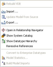
The Metadata menu contains the following actions:
Rebuild VDB - Performs a complete re-validation of the contents of the selected VDB.
Import... - Launches Import Wizard.
Update Model from Source - If the selected model is a relational source model that was originally created via JDBC Import, then the model will be updated based on changes in the database schema.
Export... - Launches Export Wizard.
Open in Relationship Navigator - Opens the Relationship Navigator view and displays the direct relationships to the selected object.
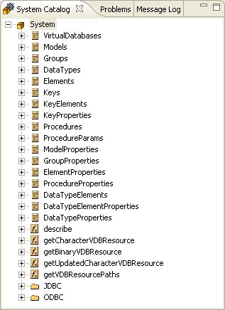
Show System Catalog - Opens the System Catalog View.
Show Datatype Hierarchy - Opens the Datatype Hierarchy View.
Re-resolve References - Analyzes references within models to other model components.
Convert to Enterprise Datatypes - Adds an additional property to simple datatypes within your selected schema model to label them as enterprise datatypes.
Show Model Statistics - Opens the Model Statistics dialog for the selected model.
Build Model Imports - Reconciles all model import dependencies for the selected model.
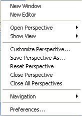
The Window menu shown below contains no Teiid Designer-specific actions. See Eclipse Workbench documentation for details.
- 4.1. Model Explorer View
- 4.2. Outline View
- 4.3. UDFs View
- 4.4. Connectors View
- 4.5. Properties View
- 4.6. Description View
- 4.7. Editors
- 4.8. Problems View
- 4.9. Message Log View
- 4.10. Preview Results View
- 4.11. Search Results View
- 4.12. Datatype Hierarchy View
- 4.13. Model Classes View
- 4.14. System Catalog View
- 4.15. Database Structure View
- 4.16. SQL History View
- 4.17. Connections View
- 4.18. SQL Editor View
- 4.19. SQL Results View
Go To: Table of Contents
Teiid Designer provides various views to display and allow editing of models and model content. This section describes each view in detail.
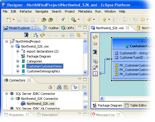
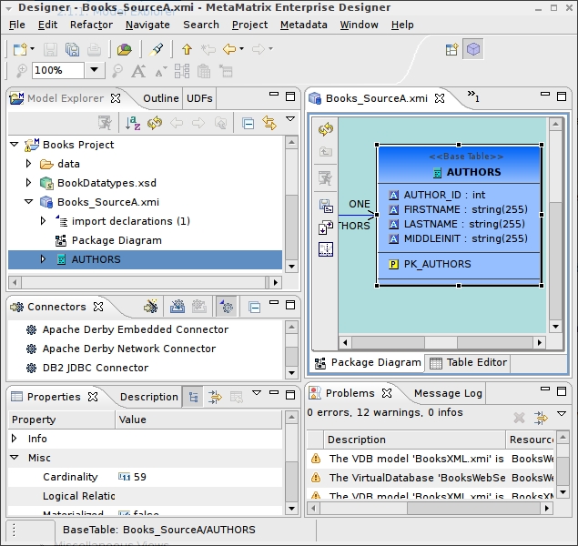
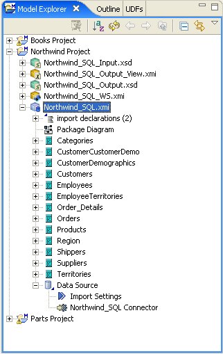
Teiid Designer allows you manage multiple projects containing multiple models and any corresponding or dependent resources. The Model Explorer provides a simple file-structured view of these resources.
The Model Explorer (shown below) is comprised of a toolbar and a tree view.
The toolbar consists of nine common actions:
 Preview Data - Executes a simple preview query (SELECT * FROM ).
 Sort Model Contents - Sorts the contents of the models based on object type and
alphabetizing.
Sort Model Contents - Sorts the contents of the models based on object type and
alphabetizing.
 Refresh Markers - Refreshes error and warning markers for objects in tree.
 Back - Displays the last "Go Into" location. (See Eclipse Help)
 Forward - Displays the next "Go Into" location. (See Eclipse Help)
 Up - Navigates up one folder/container location. (See Eclipse Help)
 Collapse All - Collapses all projects.
 Link with Editor - When object is selected in an open editor, this option
auto-selects and reveals object in Model Explorer.
Link with Editor - When object is selected in an open editor, this option
auto-selects and reveals object in Model Explorer.
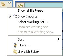
 Additional Actions
The additional actions are shown in the following figure:
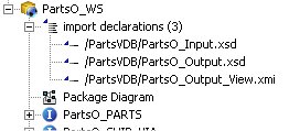
If Show Model Imports is checked, the imports will be displayed
directly under a model resource as shown below.
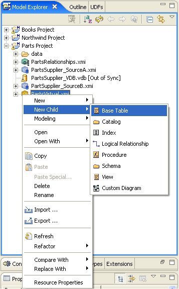
Selecting specific objects in the Model Explorer provides a context from which the Teiid Designer presents a customized menu of available actions.
Selecting a view model, for instance, results in a number of high-level options to manage edit model content, perform various operations and provides quick access to other important actions available in Teiid Designer. These may include specialized actions based on model type.
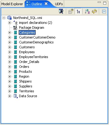
The Outline View is a utility view which provides both at tree view dedicated to a specific model (open in an editor) and a scaled thumbnail diagram representative of the diagram open in the corresponding Diagram Editor.
You can show the Outline View by clicking on its tab. If there is no open editors, the view indicates that "An Outline is not available." If a Model Editor is open, then the root of the displayed tree will be the model for the editor that is currently in focus in Teiid Designer (tab on top).
This tree view provides the same basic editing and navigation behavior as the Model Explorer. One additional capability is the drag and drop feature which provides re-ordering and re-parenting of objects in a model.
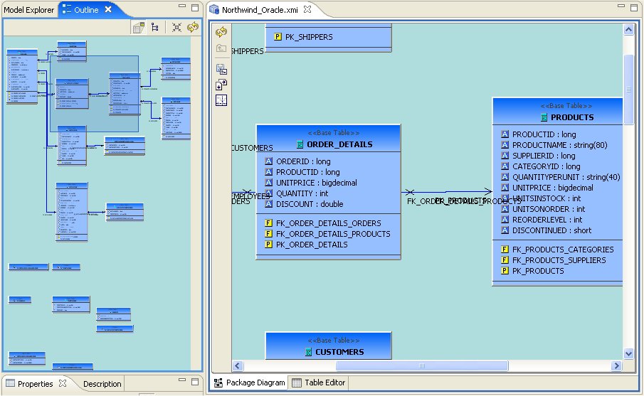
The Outline View also offers you a way to view a thumbnail
sketch of your diagram regardless of its size. To view this diagram
thumbnail from the Outline panel, click the Diagram Overview button ![]() at the top of the view. The diagram overview displays in the Outline View.
at the top of the view. The diagram overview displays in the Outline View.
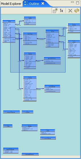
The view contains a thumbnail of your entire diagram. The shaded portion represents the portion visible in the Diagram Editor view.
To move to a specific portion of your diagram, click the shaded area and drag to the position you want displayed in the Diagram Editor view.
User Defined Functions extend the basic set of functions you can use within data access applications that use Teiid Designer or even within your transformation queries that you use to model View Metadata. Your organization needs to develop Java logic to perform these functions and manage these functions through the Teiid Designer Console. For more information about this complete process, see Creating Custom User-Defined Functions.
Before you can model the user-defined functions, you must have exported the User Defined Functions metadata model from Teiid Designer using the Teiid Designer Console. You should have placed this file in your local directory so that you can open it.
The User Defined Functions model uses a special metamodel, the Function metamodel, which is limited to constructs for this specific purpose. Therefore you cannot create a new model using this metamodel, nor should you use this model in a project or as a source for View Metadata models.
Users can edit their User Defined Functions model from within the UDFs view shown below. The basic functionality of the UDFs view is identical to the Model Explorer view but focused the single FunctionsDefinitions model.
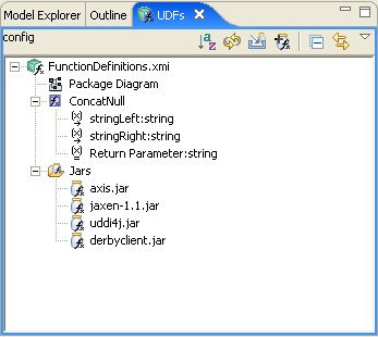
The view's toolbar actions include:
- Sort Model Contents - Sorts the contents of the models based on object type and alphabetizing.
- Refresh Markers - Refreshes error and warning markers for objects in tree.
 Import UDF Extension Jar -Import your custom UDF extension jar files.
 Add Connector Jar to UDF - Add connector jar to UDF model. This allows using dual use extension jars.
- Collapse All - Collapses the tree view.
- Link with Editor - When object is selected in an open editor, this option
auto-selects and reveals object in Model Explorer.
You can delete your UDF jars by right-click select Delete Jars action.
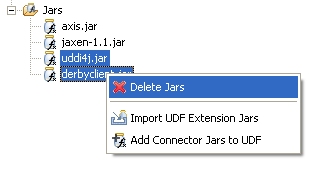
Both UDF jars and connector extension jars are utilized by Teiid Designer during VDB execution and data Preview. This provides the ability to utilize a common extension jar to deliver both user defined function code and custom connector code. To facilitate this scenerio, the UDFs view contains an Add Connector Jar to UDF action.
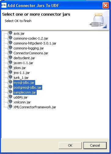
To add an existing connector jar to your UDF:
Step 1:
Select the Add Connector Jar to UDF toolbar button
![]() or select the UDF jars folder or jar and right-click select the same
action.
or select the UDF jars folder or jar and right-click select the same
action.
Step 2 : In the selection dialog below, select one or more connector jars and choose OK to finish.
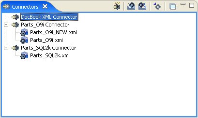
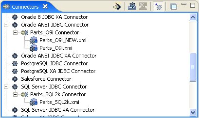
The Connectors View provides a means to display and manage (add or remove) connectors and source bindings in Teiid Designer. For more information on Connectors, see Manage Connectors.
To show the Connectors View click Views > Show View > Other... to display the Show View dialog. Choose Teiid Designer > Connectors view and hit OK.
The view's toolbar actions include:
 Create New Connector - Launches New Connector wizard.
 Import Connectors - Imports connectors from a *.cdk file.
 Export Connectors - Exports selected connectors to *.cdk file. This action
provides a means to transfer your source connection information
between Teiid Designer workspaces.
Export Connectors - Exports selected connectors to *.cdk file. This action
provides a means to transfer your source connection information
between Teiid Designer workspaces.
 Show/Hide Connector Types - Shows or hides connector types in tree view.
- Collapse All - Collapses the tree view.
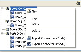
You can also access these actions via the right-click menu as shown below. Note that the Clone connector action creates a new connector whose property values are set with those of the originally selected connector.
You can show/hide the connector types by toggling the action ![]() in the toolbar.
in the toolbar.
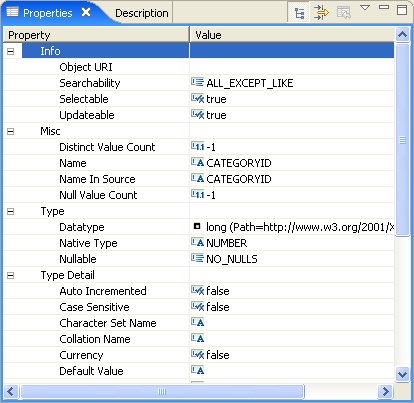
The Properties View provides editing capabilities for the currently selected object in Teiid Designer . The selection provided by whichever view or editor is currently in focus will determine the its contents.
To edit a property, click a cell in the Value column. As in the Table Editor, each cell provides a UI editor specific to the property type. See Editing Table Properties for a detailed summary.
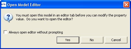
If the model for the object being edited is not open in an editor, a dialog may appear confirming the attempt to modify the model and asking the user to confirm or cancel. This dialog can be prevented by checking the preference "Always open editor without prompting". You can re-set/uncheck this property via the Teiid Designer's main preference page.
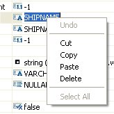
Properties can also be edited via a right-click menu presented below.
The Properties toolbar contains the following actions:
 Show Categories - toggles between categorized properties and flat alphabetical properties list.
 Show Advanced Properties - shows/hide advanced properties (if available).
 Restore Default Value - for a selected property, this action will reset the current to a default value (if available).
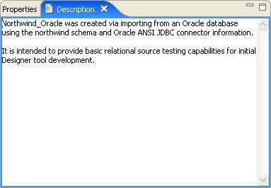
The Description View provides a means to display and edit (add, change or remove) a description for any model or model object. To show the Description View click " Views > Show View > Other... " to display the Show View dialog. Choose " Teiid Designer > Description " view and hit OK .
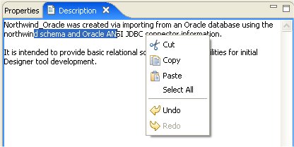
You can click in the text field and edit in a similar fashion with standard text editing. Below is a list of available right-click edit actions.
Editors are the UI components designed to assist editing your models and to maintain the state for a given model or resource in your workspace. When editing a model, the model will be opened in a Model Editor. Editing a property value, for instance, will require an open editor prior to actually changing the property.
Any number of editors can be open at once, but only one can be active at a time. The main menu bar and toolbar for Teiid Designer may contain operations that are applicable to the active editor (and removed when editor becomes inactive).
Tabs in the editor area indicate the names of models that are currently open for editing. An asterisk (*) indicates that an editor has unsaved changes.

By default, editors are stacked in the editors area, but you can choose to tile them vertically, and or horizontally in order to view multiple models simultaneously.
The Teiid Designer provides main editor views for XMI models and VDBs.
The Model Editor contains sub-editors which provide different views of the data or parts of data within a model. These sub-editors, specific to model types are listed below.
Diagram Editor - All models except XML Schema models.
Table Editor - All models.
Simple Datatypes Editor - XML Schema models only.
Semantic Editor - XML Schema models only.
Source Editor - XML Schema models only.
The VDB Editor contains sub-editors which provide different views of the data or parts of data within a VDB. These sub-editors include.
Overview - View and manage contents of VDB.
Problems - Display errors and warnings within VDB and models.
Indexes - View indexes generated for model data within VDB.
User Files - Manage additional VDB resources or artifacts.
Web Services - Define and view WSDL.
Execute - Create and change connectors and execute queries.
In addition to general Editors for models, there are detailed editors designed for editing specific model object types. These "object" editors include:
Transformation Editor - Manages Transformation SQL for Relational View Base Tables, Procedures and XML Service View Operations.
Choice Editor - Manages properties and criteria for XML choice elements in XML Document View models.
Input Editor - Manages Input Set parameters used between Mapping Classes in XML Document View models.
Recursion Editor - Manages recursion properties for recursive XML Elements in XML Document View models.
Operation Editor - Manages SQL and Input Variables for Web Service Operations.
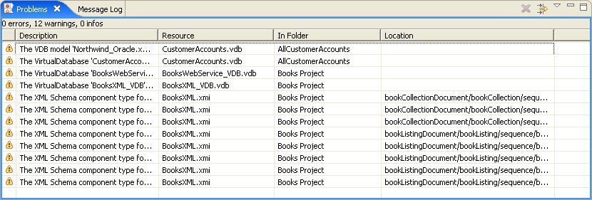
The Problems View displays validation errors, warnings, or information associated with a resource contained in open projects within your workspace.
By default, the Problems View is included in the Teiid Designer perspective. If the Problems View is not showing in the current perspective click Views > Show View > Other > Teiid Designer > Problems.
There are 5 columns:
Severity - Indicates the severity of the line item (i.e., error
 , warning
  , or info
  ).
).
Description - A description of the line item.
Resource - The name of the resource.
In Folder - The project name.
Location - Model object within the resource that has a validation error.
Click the upside-down triangle
![]() icon to open the view menu.
icon to open the view menu.
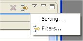
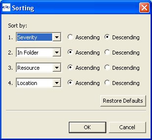
The Sorting action presents a dialog which enables sorting of the problems by severity, resource, and location.
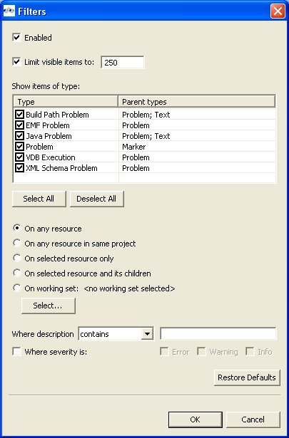
The Filters action presents a dialog which enables filtering of the problems by total number, type, resource, severity, and description.
Additional actions are available by selecting a problem and right-click to open a context menu.
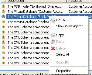
Go To - will open the appropriate editor and select the affected/referenced object.
Show In Navigator - Opens the Basic > Navigator view (if not open) and expands file system tree and reveals applicable resource.
Copy - Copies the problem information to the system clipboard.
Paste - Pastes the problem information located in the system clipboard ( if applicable ) into the curor location for a specified text editor.
Delete - Deletes the selected problem rows ( if applicable ).
Select All - selects all problems in the table.
Quick Fix - (Not yet implemented in Teiid Designer).
Properties - displays a dialog containing additional information.
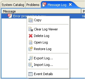
The Message Log view provides a console-based view of any errors or warnings that may occur during your Teiid Designer session.
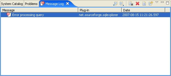
You can perform various operations on the content of the viewer via the toolbar actions or use the right-click menu shown below.
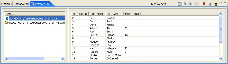
Executing the
Preview Data
action
![]() , will result in the query results being displayed in the Preview
results view, shown below.
, will result in the query results being displayed in the Preview
results view, shown below.
The view's toolbar actions include:
 Show Query Results - Shows query results in table row or XML format.
 Show Query Plan Tree - Shows query plan in tree format.
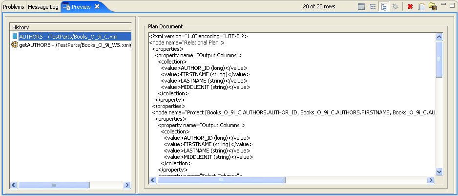
 Show Query Plan Document - Shows query plan in xml document format.
 Show Debug Log - Shows debug log file contents.
 Close the Selected Results - Removes the selected results from the view.
- Copy Results to Clipboard - Copies selected results as text to the system clipboard.
 Save Results to File - Provides a file dialog to save selected results to a text file on
file system.
Save Results to File - Provides a file dialog to save selected results to a text file on
file system.
Tip
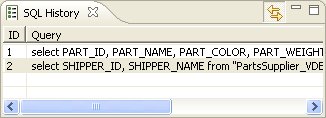
The History list can be sorted alphabetically (or reverse) by clicking the "History" column header.
Tip
The tooltip for each History object will display the underlying base SQL text used in the query.
Because the Preview Data feature is just that, a preview, you are limited to maximum number of rows returned rows. This value is a user preference and can be changed from its default value by selecting Preferences > Teiid Designer and changing the Preview Data's row count limit value.
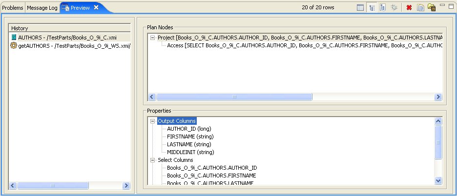
By selecting the Show Query Plan Tree toolbar action the SQL table results are replaced with a tree view of the underlying Query plan and corresponding properties.
By selecting the Show Query Plan Document toolbar action the SQL table results are replaced with an XML document view of the underlying Query plan.
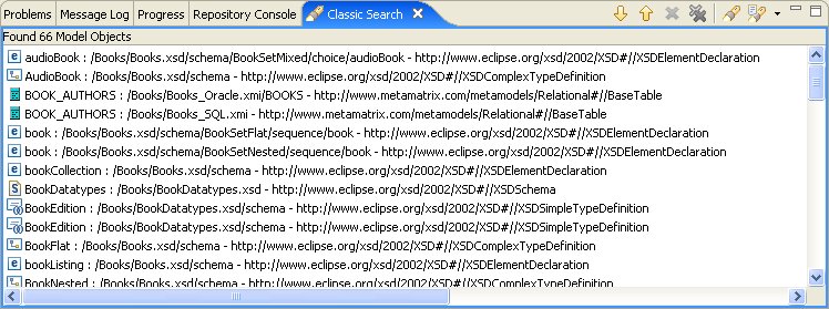
Below is an example set of search results. The view contains rows representing matches for your search parameters. You can double-click a entry and the object will be opened and selected in an editor and/or the VDB Explorer if applicable.
The toolbar actions for the Search Results view are:
 Show Next Match - Navigates down one row in the view.
 Show Previous Match - Navigates up one row in the view.
 Remove Selected Matches - Removes selected results from the view.
 Remove All Matches - Clears the view.
- Search - Launches the MoTeiid Designerearch Dialog.
 Previous Search Results - Select previous search results from history.
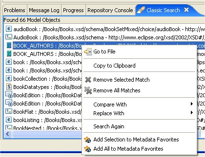
You can also perform some of these actions via the right-click menu:
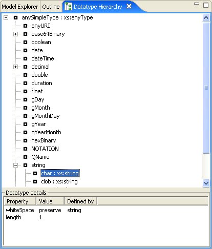
To open Teiid Designer's Datatype Hierarchy view, select the main menu's Views > Show View > Other... and select the Teiid Designer > Datatypes view in the dialog.
To open Teiid Designer's System Catalog view, select the main menu's Views > Show View > Other... and select the Teiid Designer > System Catalog view in the dialog..
Go To: Table of Contents
Editors are the UI components designed to assist editing your models and to maintain the state for a given model or resource in your workspace. When editing a model, the model will be opened in a Model Editor. Editing a property value, for instance, will require an open editor prior to actually changing the property.
Any number of editors can be open at once, but only one can be active at a time. The main menu bar and toolbar for Teiid Designer may contain operations that are applicable to the active editor (and removed when editor becomes inactive).
Tabs in the editor area indicate the names of models that are currently open for editing. An asterisk (*) indicates that an editor has unsaved changes.
By default, editors are stacked in the editors area, but you can choose to tile them vertically, and or horizontally in order to view multiple models simultaneously.
Editors also contain sub-editors which provide different views of the data or parts of data within a model. These sub-editors, specific to model types are listed below.
Diagram Editor - All models except XML Schema models.
Table Editor - All models.
Simple Datatypes Editor - XML Schema models only.
Semantic Editor - XML Schema models only.
Source Editor - XML Schema models only.
In addition to general Editors for models, there are detailed editors designed for editing specific model object types. These "object" editors include:
Transformation Editor - Manages Transformation SQL for Relational View Base Tables, Procedures and XML Service View Operations.
Choice Editor - Manages properties and criteria for XML choice elements in XML Document View models.
Input Editor - Manages Input Set parameters used between Mapping Classes in XML Document View models.
Recursion Editor - Manages recursion properties for recursive XML Elements in XML Document View models.
Operation Editor - Manages SQL and Input Variables for Web Service Operations.
The Model Editor is comprised of sub-editors which provide multiple views of your data. The Diagram Editor provides a graphical while the Table Editor provides spreadsheet-like editing capabilities. This section describes these various sub-editors.
The Diagram Editor provides a graphical view of the a set of model components and their relationships.
Several types of diagrams are available depending on model type. They include:
 Package Diagram
 Custom Diagram
 Transformation Diagram
 Mapping Diagram
- Mapping Transformation Diagram
 Relationship Diagram
You can customize various diagram visual properties via Diagram Preferences.
Each diagram provides actions via the Main toolbar, diagram toolbar and selection-based context menus. These actions will be discussed below in detail for each diagram type.
When a Diagram Editor is in focus, a set of common diagram actions is added to the application's main toolbar.
The actions include:
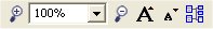
 Zoom In
 Zoom to Level
 Zoom Out
 Increase Font Size
 Decrease Font Size
 Perform Diagram Layout
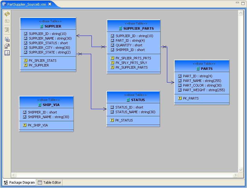
The Package Diagram provides a graphical view of the contents of a model container, be it the model itself, a relational catalog or schema.
Package Diagram toolbar actions include:
 Refresh Diagram - Re-draws diagram.
 Show Parent Diagram - Navigates to diagram for parent object (if available).
- Preview Data - Executes a simple preview query (SELECT * FROM ).
 Save Diagram as Image - Save the diagram image to file in JPG or BMP format.
 Modify Diagram Printing Preferences - Modify page layout information for printing diagrams. Includes margins, orientation, etc...

 Show/Hide Page Grid - Show current page boundaries as grid in diagram.
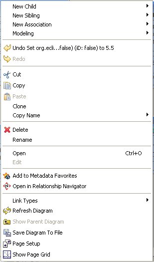
Context menus provide a flexible means to edit model data, especially from Package Diagrams. Each Package Diagram represents the contents of some container (i.e. Model, Category, Schema, etc...), so New Child, New Sibling and New Association actions are almost always available in addition to standard Edit actions (Delete, Cut, Copy, Paste, Rename, Clone).
A sample context menu for a relational base table is shown below.
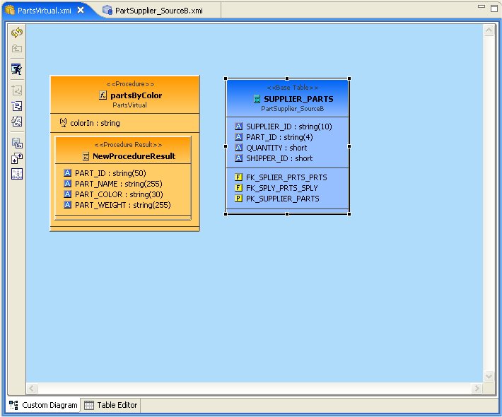
The Custom Diagram represents a view of user-defined model objects. Unlike Package Diagrams, Custom Diagrams can contain objects that are not only unrelated, but can be from different containers and even models.
Custom Diagram toolbar actions include:
- Refresh Diagram - Re-draws diagram.
- Show Parent Diagram - Navigates to diagram for parent object (if available).
- Preview Data - Executes a simple preview query (SELECT * FROM ).
 Add To Diagram - Add objects selected in Model Explorer to diagram.
 Remove From Diagram - Removed objects selected in diagram from diagram.
 Clear Diagram - Remove all objects from diagram.
- Save Diagram as Image - Save the diagram image to file in JPG or BMP format.
- Modify Diagram Printing Preferences - Modify page layout information for printing diagrams. Includes margins, orientation, etc...
- Show/Hide Page Grid - Show current page boundaries as grid in diagram.
Since Custom Diagrams do not represent represents the contents of container objects(i.e. Model, Category, Schema, etc...) its context menus are limited to adding/removing objects from diagram and basic diagram-related display options.
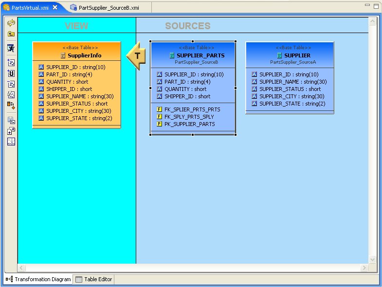
The Transformation Diagram represents a view of the relationships defined by the source inputs described in a view table's SQL transformation.
Transformation Diagram toolbar actions include:
- Refresh Diagram - Re-draws diagram.
- Show Parent Diagram - Navigates to diagram for parent object (if available).
- Preview Data - Executes a simple preview query (SELECT * FROM ).
- Add Transformation Sources - Add selected sources to transformation.
 Add Union Transformation Sources - Add selected sources as union sources.
- Remove Transformation Sources - Removed sources selected in diagram from transformation.
- Clear Transformation - Remove all sources from transformation.
 Open Transformation Reconciler dialog
- Save Diagram as Image - Save the diagram image to file in JPG or BMP format.
- Modify Diagram Printing Preferences - Modify page layout information for printing diagrams. Includes margins, orientation, etc...
- Show/Hide Page Grid - Show current page boundaries as grid in diagram.
Context menus for the
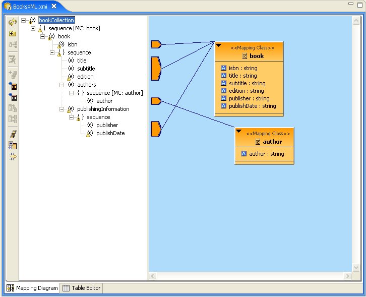
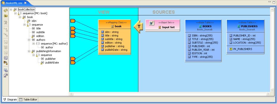
The Mapping Diagram represents a view of the mapping between virtual mapping class columns and XML document elements. This mapping defines how source data is transformed from row-based results into XML formatted text.
Mapping Diagram toolbar actions include:
- Refresh Diagram - Re-draws diagram.
- Show Parent Diagram - Navigates to diagram for parent object (if available).
 Show Mapping Transformation Diagram - Show detailed mapping transformation diagram for selected mapping class.
- Preview Data - Executes a simple preview query (SELECT * FROM ).
 Generate Mapping Classes - Generate mapping classes for the selected XML document root element.
 New Mapping Class - Insert new mapping class referenced to the selected XML document element or attribute..
 New Staging Table - Insert new staging table referenced to the selected XML document element or attribute.
 Merge Mapping Classe - Merge selected mapping classes.
 Split Mapping Class - Split selected mapping class.
 Display All Mapping Classes
 Show Mapping Class Columns
- Filter Displayed Mapping Classes with Selection
Context menus for Mapping Diagrams provide Edit capability to the mapping class in addition to mapping class manipulation actions (i.e. Merge Mapping Classes, Split Mapping Class, etc..)
The Mapping Transformation Diagram is identical to a Transformation Diagram except for displaying an Input Set and possibily Staging Tables as sources for the Mapping Class's transformation.
Mapping Transformation Diagram toolbar actions include:
- Refresh Diagram - Re-draws diagram.
- Show Parent Diagram - Navigates to diagram for parent object (if available).
- Preview Data - Executes a simple preview query (SELECT * FROM ).
 New Mapping Link - Create a mapping link between selected mapping extent (i.e. XML element or attribute) and mapping class column.
 Remove Mapping Link - Delete mapping link between selected mapping extent (i.e. XML element or attribute) and mapping class column.
- Add Transformation Sources - Add selected sources to transformation.
- Add Union Transformation Sources - Add selected sources as union sources.
- Remove Transformation Sources - Removed sources selected in diagram from transformation.
- Clear Transformation - Remove all sources from transformation.
- Open Transformation Reconciler dialog
- Save Diagram as Image - Save the diagram image to file in JPG or BMP format.
- Modify Diagram Printing Preferences - Modify page layout information for printing diagrams. Includes margins, orientation, etc...
Context menus for Mapping Transformation Diagrams identical capabilities to the Transformation Diagram with the addition of managing and editing Input Sets.
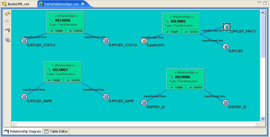
The Relationship Diagram represents a view of relationships between sources and targets defined in your Relationship models as well as the relationships and hierarchy between relationship types.
Relationship Diagram toolbar actions include:
- Refresh Diagram - Re-draws diagram.
- Show Parent Diagram - Navigates to diagram for parent object (if available).
 Remove From Relationship - Removes the selected source or targets from a relationship.
- Save Diagram as Image - Save the diagram image to file in JPG or BMP format.
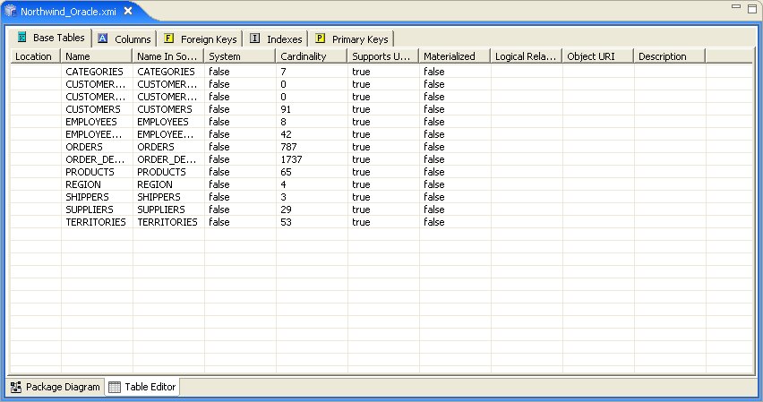
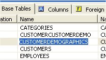
The Table Editor provides a table-based object type structured view of the contents of a model. The figure below shows a relational model viewed in the Table Editor. Common object types are displayed in individual folders/tables. All base tables, for instance, are shown in one table independent of their parentage.
You can customize Table Editor properties via Table Editor Preferences.
These are the primary features of the Table Editor:
Edit existing properties.
Add, remove or edit objects, via the main Edit menu and context menu ( Cut, Copy, Paste, Clone, Delete, Rename, Insert Rows ).
Paste information from your clipboard into the table.
Print your tables.
When a
Table Editor
is in focus, the
Insert Table Rows action ![]() is added to the application's main toolbar.
is added to the application's main toolbar.
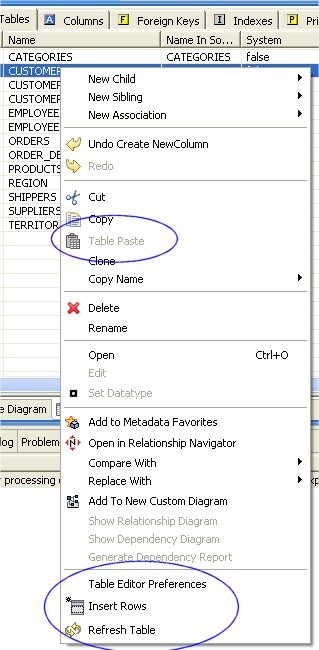
A few Table Editor actions are contributed to the right-click menu for selected table rows. These actions, described and shown below include:
Table Paste - Paste common spreadsheet data (like Microsoft Excel) to set object properties.
Table Editor Preferences - Change table editor preferences, including customizing visible properties.
Insert Rows - Create multiple new sibling objects.
Refresh Table - Refreshes the contents of the current Table Editor to insure it is in sync with the model.
You can edit properties for an object by double-clicking a table cell.
For String properties, the table cell will become an in-place text editor field.
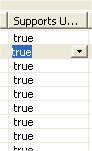
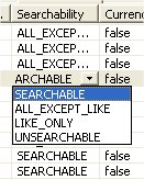
If a property is of a boolean (true or false) type or has multiple, selectable values, a combo box will be displayed to change the value.
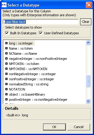
For multi-valued properties where the available values are dynamic (i.e. can change based on available models or data), a picker-button ("....") will be displayed.
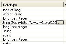
An example of of this type is the relational column datatype property. Editing via the table cell and clicking the "..." button for datatype will display the following dialog.
The Insert Rows action provides an additional way to create objects in a model. Insert Rows action performs the same function as Insert SIbling action, but allows you to create multiple children at the same time. All new rows will correspond to an object of the same type as the selected object and be located under the same parent as the selected object.
To Insert Rows in a table:
Step 1: Select a table row to insert rows after.
Step 2: Right-click select "Insert Rows" action or select the Insert Rows action on the main toolbar. The following dialog will be displayed.
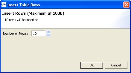
Step 3: Edit the Number of Rows value in the dialog, or use the up/down buttons to change the value.
Step 4: Select OK in dialog.
The desired number of rows (new model objects) will be added after the original selected table row.
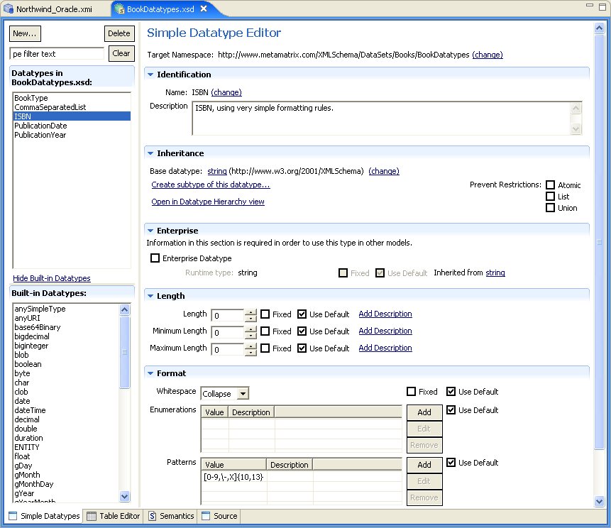
The Simple Datatype Editor provides a form-based properties view of XML Schema data.
The Semantic Editor is a tree based editor for XML Schema elements and attributes.
The Source Editor is a simple text editor which is aware of XML Schema formatting rules.
The Model Object Editors represent specialized sub-editors which are available for specific model object types.
For details, select a specific editor listed below:
A VDB, or virtual database is a container for components used to integrate data from multiple data sources, so that they can be accessed in a federated manner through a single, uniform API. A VDB contains models, which define the structural characteristics of data sources, views, and Web services. The VDB Editor, provides the means to manage the contents of the VDB as well as its deployable (validation) state.
The VDB Editor, shown below, contains six editor tabs, namely:
Overview - Manage/edit contents, description and indicates current deployable state.
Problems - Table view of any validation problems your VDB may have (i.e. Warnings and/or Errors).
Indexes - Provides viewable summary of various Index files utilized at run-time.
User Files - Provides importing or attaching additional user files to the VDB archive.
Web Services - When VDB contains Web Services models, this tab provides access edit and view WSDL specific information.
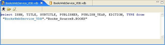
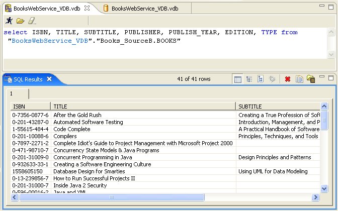
Execute - Manage source model connector bindings and actually test your data.
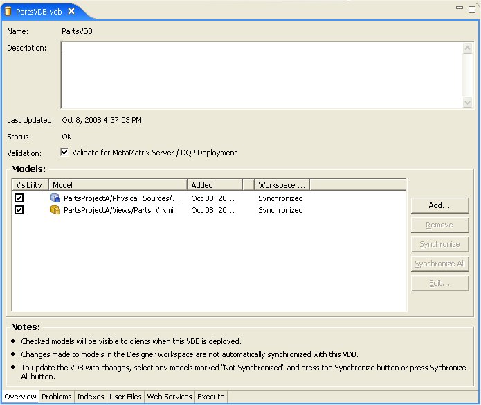
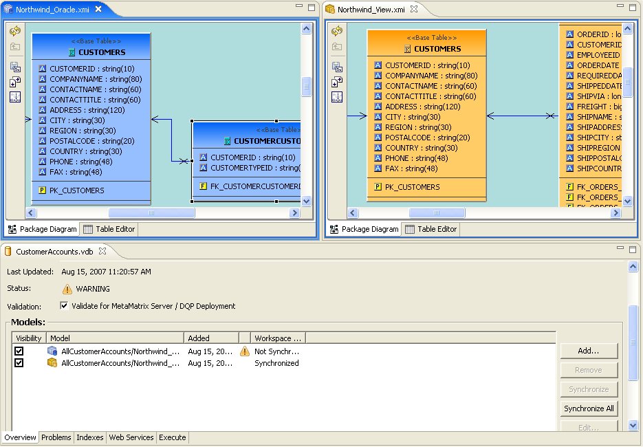
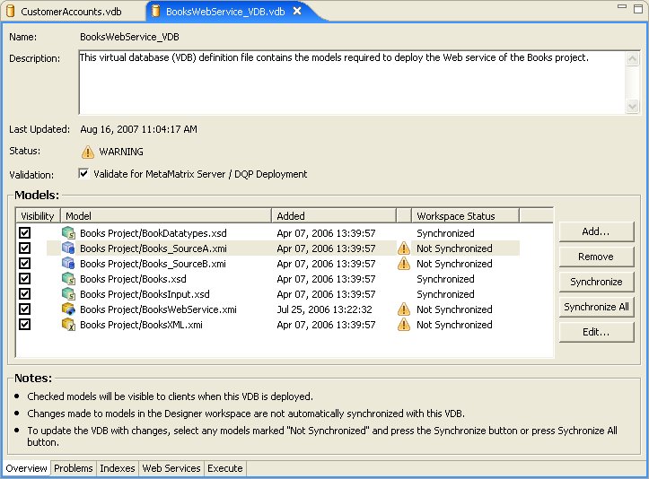
The Overview tab allows you to Manage and edit the contents, description and indicates current deployable state of your VDB.
Manage content of the VDB by using the Add... and Remove... buttons.
Synchronize and Synchronize All button provide a easy way to update the contents of your VDB if changes have occurred to one or more models in your local workspace. Remember, when a model is added to a VDB, an exact copy of that model is added the the VDB archive. If a model has changed since it was added to a VDB, a Not Synchronized message will be visible in the Workspace Status column.
An example VDB containing multiple models is shown below (including models that have been modified in the workspace after they were added to the VDB).
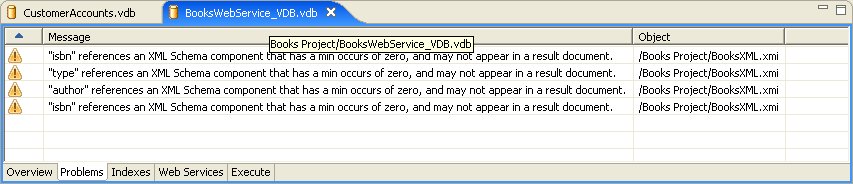
The Problems tab displays all errors and warnings for your VDB and its contained models.
The Indexes tab provides visual access to the underlying metadata that will be deployed to the server and accessed at runtime.
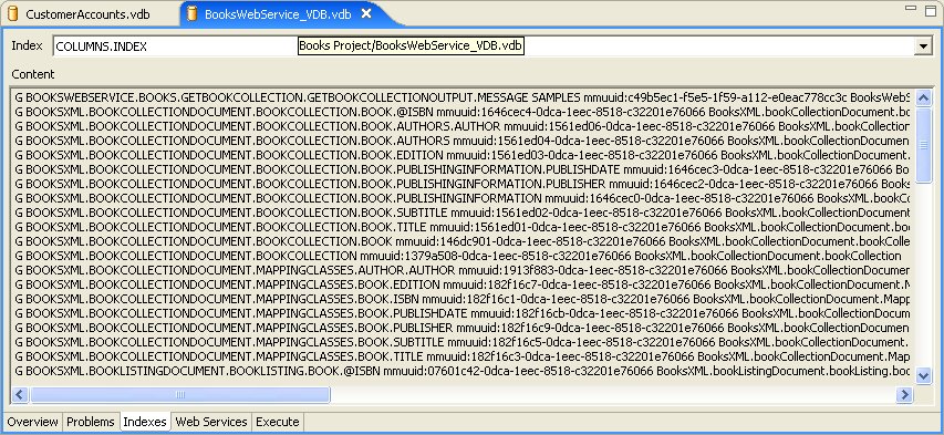
You can add additional artifacts or files to your VDB via the User Files tab in the VDB Editor. Select the Add... button and locate/select files from your local file system.
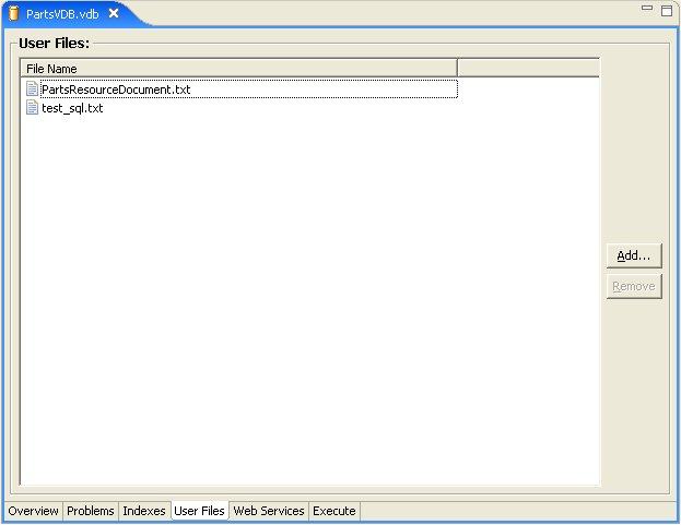
The Web Services tab provides a means to specify the target namespace URL for your WSDL and to display a preview of that WSDL.
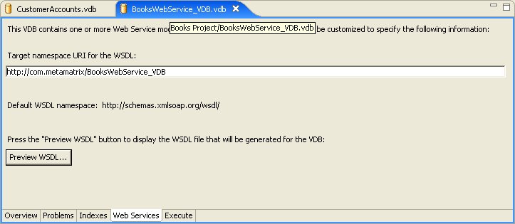
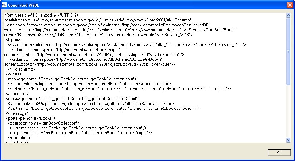
The Execute tab provides the capability to create and edit connectors for each source model in your VDB and to launch the SQL Explorer to query your data.
For more information on Connectors, see Manage Connectors.
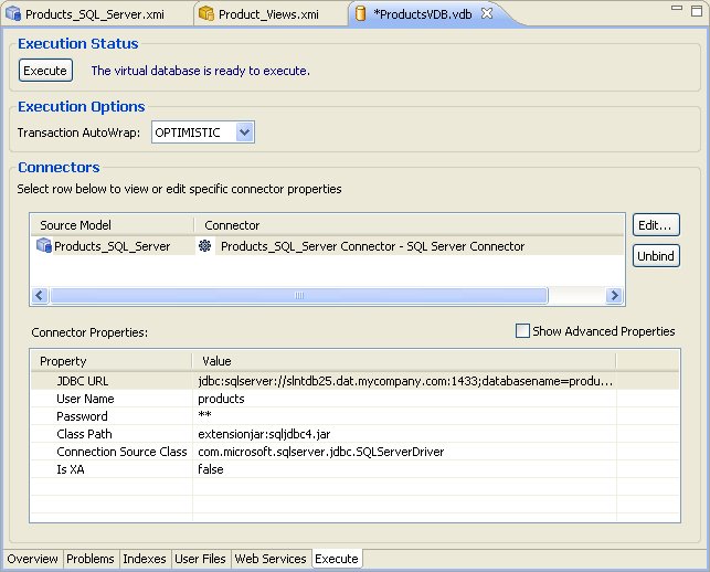
Go To: Table of Contents
The Import Wizard provides a means to create a model based on the structure of a data source, to convert existing metadata (i.e. WSDL or XML Schema) into a source model or to load existing metadata files into the current VDB.
To launch the Import Wizard, choose the File > Import action or select a project, folder or model in the tree and right-click choose "Import..."
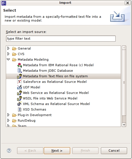
You can import files from within an archive file using the steps below.
Step 1 - In Model Explorer choose the File > Import action
 in the toolbar or select a project, folder or
model in the tree and choose Import...
in the toolbar or select a project, folder or
model in the tree and choose Import...Step 2 - Select the import option General > Archive file and click NEXT>
Step 3 - Click on the Browse button to find the archive (i.e. zip) file you wish to import. and click NEXT>
Step 4 - Open directory structure tree in left panel. Define which files from archive to import by checking/unchecking in trees.
Step 5 - Specify valid Into Folder by editing the text field, or select Browse... button to locate and select a folder or project in your workspace.
Step 6 - Click Finish.
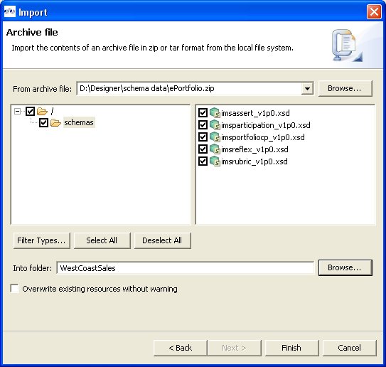
You can import files located on your local file system using the steps below.
Step 1 - In Model Explorer choose the File > Import action
in the toolbar or select a project, folder or
model in the tree and choose Import...Step 2 - Select the import option General > File system and click Next>
Step 3 - Click on the Browse button to find the archive (i.e. zip) file you wish to import. and click NEXT>
Step 4 - Open directory structure tree in left panel. Define which files to import by checking/unchecking in trees.
Step 5 - Specify valid Into Folder by editing the text field, or select Browse... button to locate and select a folder or project in your workspace.
Step 6 - Modify any Options to customize the imported files.
Step 7 - Click Finish.
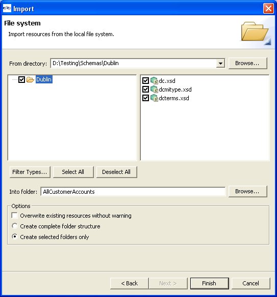
You can create relational source models from your JDBC source schema data using the steps below.
Note
Depending the detail provided in the database connection url information and schema, Steps 5 thru 7 may not be required.
Step 1 - In Model Explorer choose the File > Import action
in the toolbar or select a project, folder or
model in the tree and choose Import...Step 2 - Select the import option Metadata Modeling > Metadata from JDBC Database and click Next>
Step 3 - In the Import Database via JDBC dialog, select existing or previous source configuration or press Sources... to create new source configurations.
Step 4 - After selecting Source, input password and press Connect to Database. Press Next> (or Finish> if enabled)
Step 5 - On the Select Database Metadata page, select the types of objects in the database to import. Press Next> (or Finish> if enabled).
Step 6 - On the Select Database Objects page, view the contents of the schema, or change selections. Select which database schema objects will be used to construct relational objects. Press Next> (or Finish> if enabled)
Step 7 - On the Specify Import Options page, specify desired Model Name as well as any other options used to customize the constructed relational objects. Press Finish> to complete.
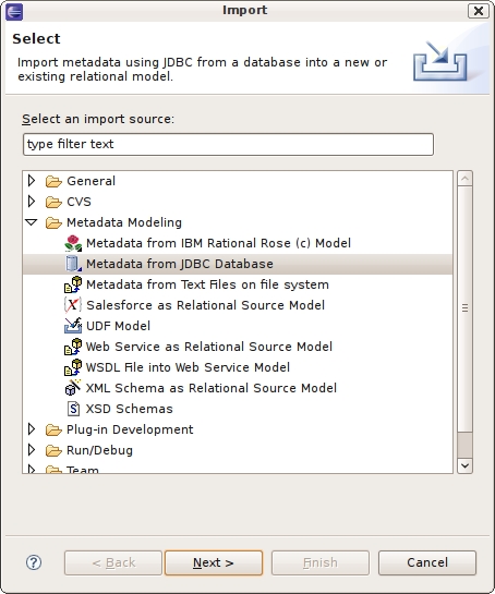
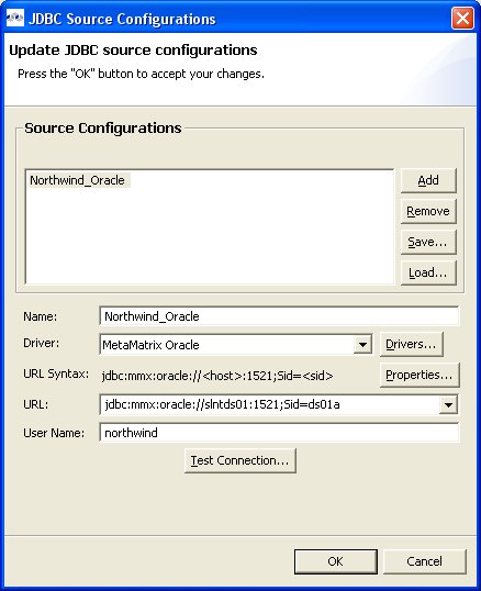
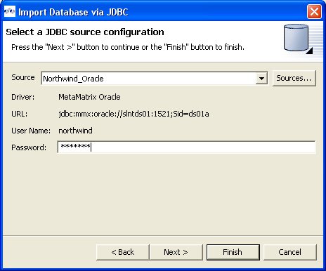
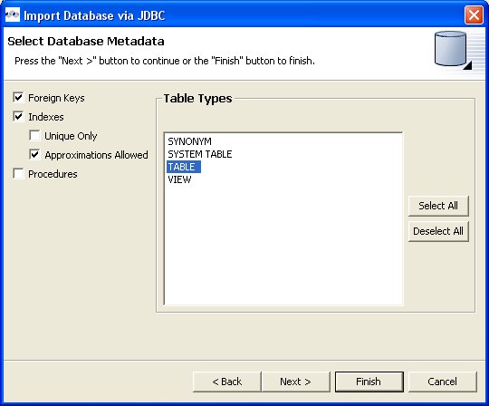
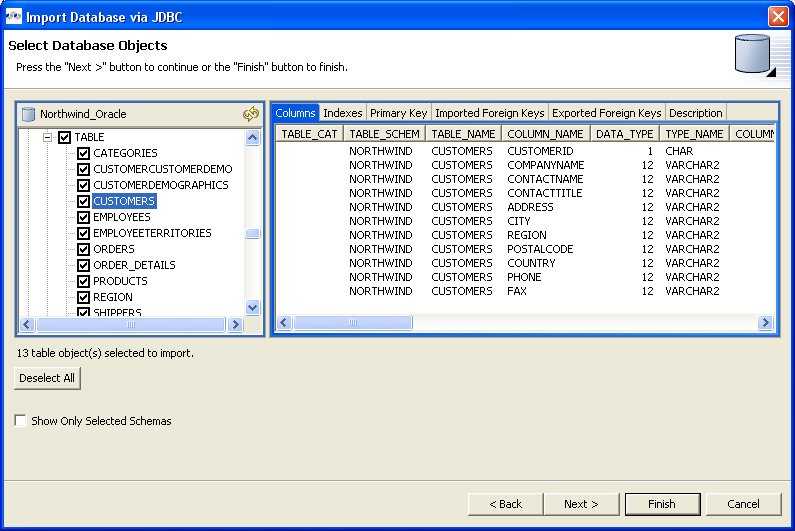

The Teiid Designer provides various import options for translating specific text file metadata into models. This is accomplished via the Import > Metadata from Text Files on file system option.
Step 1 - In Model Explorer choose the File > Import action
in the toolbar or select a project, folder or
model in the tree and choose Import...Step 2 - Select the import option Metadata Modeling > Metadata from Text Files on file system and click Next>
Step 3 - Select an import type via the drop-down menu shown below.

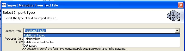
These steps required for each type are defined below:
To create relational tables from imported text file metadata:
Perform Steps 1 thru 3 (above) and select the Relational Tables import type, then click Next >
Step 4 - In the next page, you'll need to provide a source text file containing the metadata formatted to the specifications on the previous page.
Step 5 - Select an existing relational model as the target location for your new relational components using the Browse... button to open the Relational Model Selector Dialog. Select a relational model from your workspace or specify a unique name to create a new model.
Step 6 - Select any additional options and choose Finish.
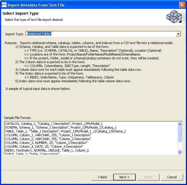
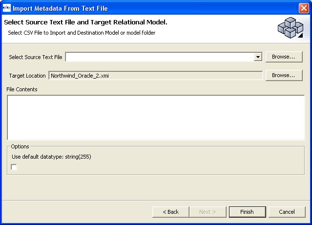
To create relational virtual tables from imported text file metadata:
Perform Steps 1 thru 3 (above) and select the Relational Virtual Tables import type, then click Next >
Step 4 - In the next page, you'll need to provide a source text file containing the metadata formatted to the specifications on the previous page.
Step 5 - Select an existing relational virtual model as the target location for your new model components using the Browse... button to open the Virtual Model Selector Dialog. Select a virtual relational model from your workspace or specify a unique name to create a new model.
Step 6 - Select Finish.
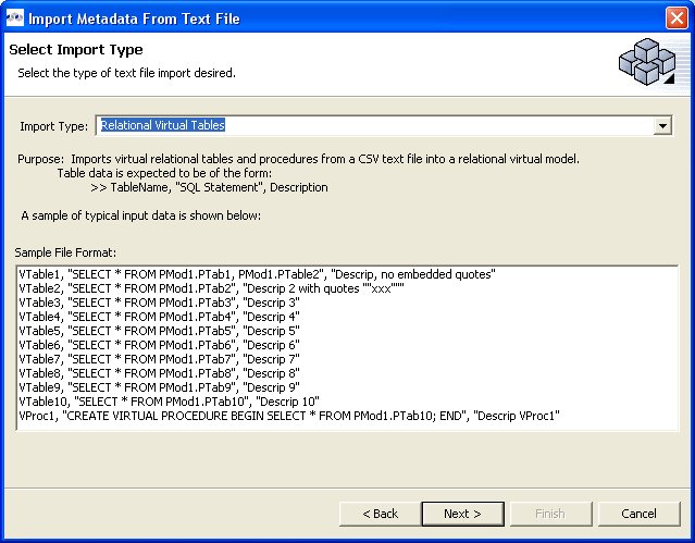
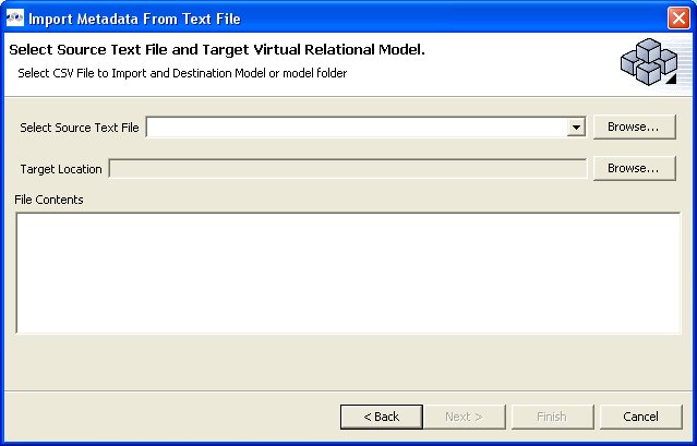
To create relationships from imported text file metadata:
Perform Steps 1 thru 3 (above) and select the Relationships import type, then click Next >
Step 4 - In the next page, you'll need to provide a source text file containing the metadata formatted to the specifications on the previous page.
Step 5 - Select an existing relationship model as the target location for your new model components using the Browse... button to open the Relationship Model Selector Dialog. Select a relationship model from your workspace or specify a unique name to create a new model.
Step 6 - Select Finish.
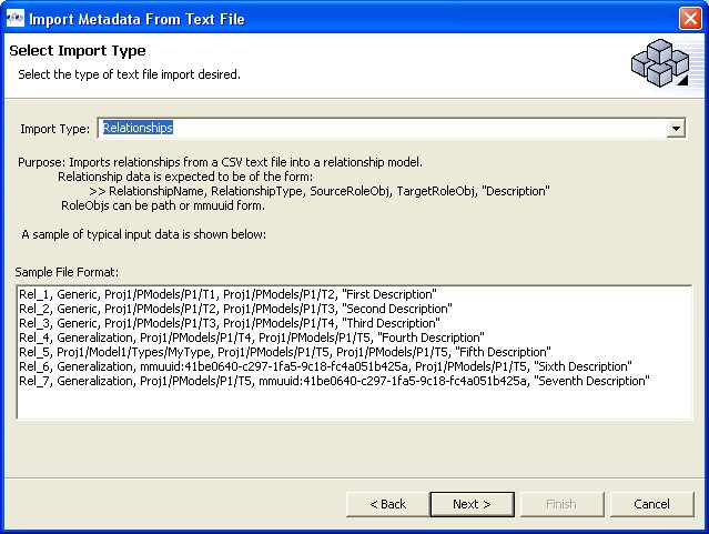
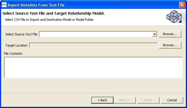
To create datatypes from imported text file metadata:
Perform Steps 1 thru 3 (above) and select the Datatypes import type, then click Next >
Step 4 - In the next page, you'll need to provide a source text file containing the metadata formatted to the specifications on the previous page.
Step 5 - Select an existing datatype model as the target location for your new model components using the Browse... button to open the Datatypes Model Selector Dialog. Select a datatypes model from your workspace or specify a unique name to create a new model.
Step 6 - Select any additional options and choose Finish.
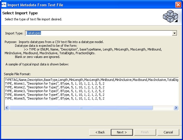
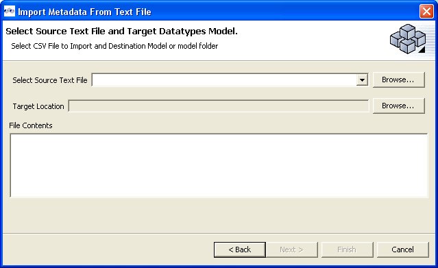
In addition to creating relational source models by importing your metadata (Import Relational Data ) you can also turn your WSDL into relational models.
To create relational models from WSDL use the steps below.
Step 1 - In Model Explorer choose the File > Import action
in the toolbar or select a project, folder or
model in the tree and choose Import...Step 2 - Select the import option Metadata Modeling > Web Service as Relational Source Model and click Next>
Step 3 - On the next page provide a source WSDL file, either in your workspace, local on your file system or provide a valid URL.
Step 4 - When WSDL is defined, you'll be required to validate your WSDL via the Validate WSDL button (see above figure).
Step 5 - Specify a unique target relational model name in the Model Name field, or select an existing relational model in your workspace via the Browse... button. Click Next> when model name is defined.
Step 6 - Specify a unique target location in the Location field (i.e. project or folder) for the relational model or select an existing location in your workspace via the Browse... button. Click Next> when location is defined.
Step 7 - The next page allows you to selected individual Web Service Operations from which to create relational tables. The default behavior of this page selects all available operations in the tree. For WSDLs backed with large schemas, there may be numerous operations which may result in a very large number of tables being generated. In this case, you may wish choose a limited number of operations at a time and repeat this process using the same target relational model.
To select all of the XSD files in the directory, click the checkbox next to the folder in the left panel.
To select individual XSD files, click the checkboxes next to the files you want in the right panel
Step 5 - Click Finish. After generation the new model can be found in the specified location in your workspace..
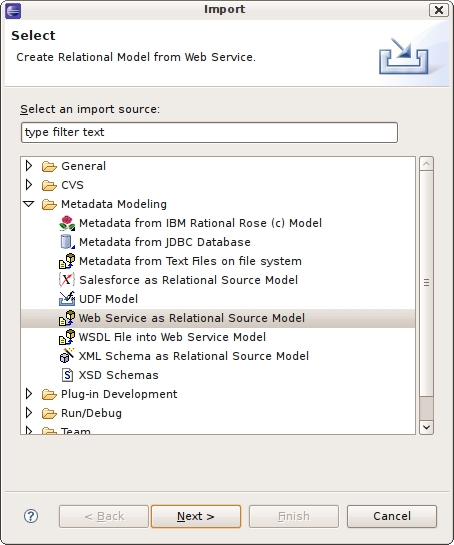
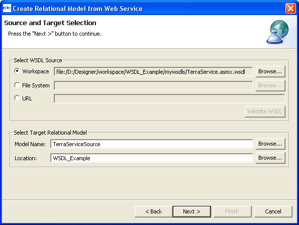
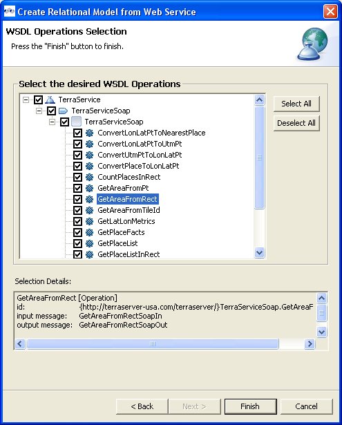
You can create a Web Service model by selecting a WSDL file in your workspace, importing WSDL files from the file system or by defining a URL. The Teiid Designer will interpret the WSDL, locate any associated or dependent XML Schema files, generate an XML View of the schema components and create a Web Service model representing the interfaces and operations defined in the WSDL.
There are three options for selecting the WSDL for your Web Service generation
Workspace Location
File System Location
URL
Detailed steps for each of these options is described below, as well as a description of how the wizard handles WSDL errors.
You can create a Web Service model by selecting a WSDL file from your workspace.
Step 1 - In Model Explorer choose the File > Import action
in the toolbar or select a project, folder or
model in the tree and choose Import...Step 2 - Select the import option Metadata Modeling > WSDL File into Web Service Model and click Next>
Step 3 - Input a valid name for your Web Service model and select the Workspace... button. Locate your workspace WSDL file in the selection dialog and click OK>.
Note
If no WSDL is selected or specified then the importer will only create an empty Web Service model. No XML Schema or XML View models will be generated.
Any referenced files (WSDLs or schemas) must either be embedded in the WSDL file or exist on your file system.
Step 4 - The next page is titled Namespace Resolution. This page identifies successful and errant WSDL namespace resolution. The main WSDL document will essentially always be resolved, since the workspace file chooser is used to obtain the path. Problems will occur when the main WSDL file imports other WSDL files that cannot be resolved. If no errors, select Next to proceed, or Finish (if enabled) to complete with default options.
Step 5 - The next page WSDL Operations Selection allows customizing the resulting content of your Web Service model by selecting/deselecting various operations and interfaces in the following dialog.
Step 6 - The next page is titled Schema Workspace Location Selection. This page lists all schemas imported by the WSDL (along with any dependent schemas referenced within schemas) as well as schemas embedded in the WSDL and indicates whether or not they are resolvable. All resolved schemas will be created in a separate file and added to the workspace. The editor panel allows you to change the default file name of the new schema file(s).
If no errors, select Next to proceed, or Finish to complete with default option
Step 7 - The last page titled XML Model Generation allows you to change the name of the XML View model if the Generate virtual XML document model is checked. Input desired name or use the default name provide. Select Finish to complete.
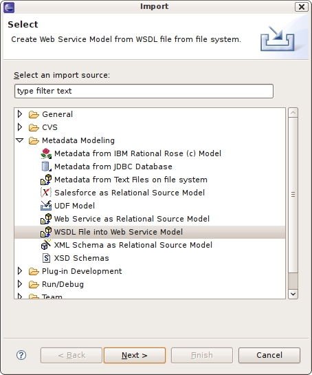
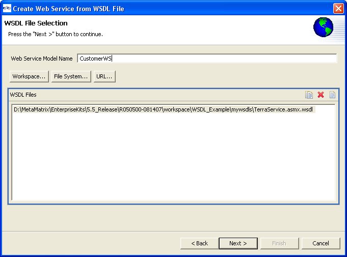
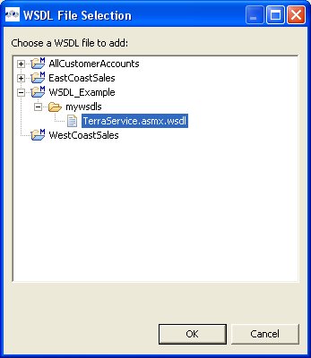
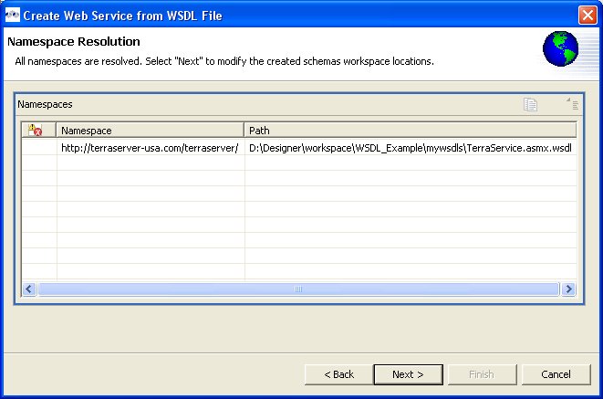
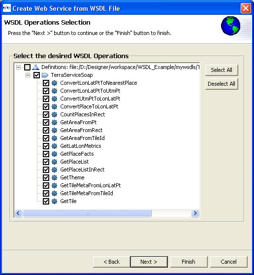
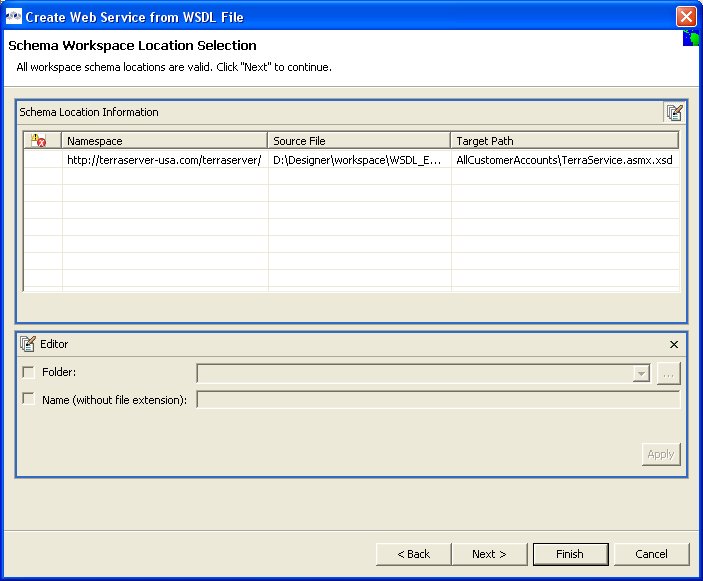
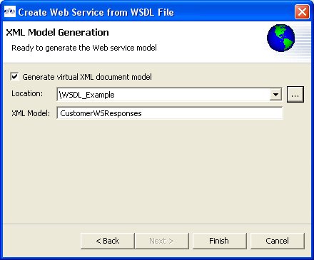
You can create a Web Service model by selecting a WSDL file from your local file system.
Step 1 - In Model Explorer choose the File > Import action
in the toolbar or select a project, folder or
model in the tree and choose Import...Step 2 - Select the import option Metadata Modeling > WSDL File into Web Service Model and click Next>
Step 3 - Input a valid name for your Web Service model and select the File System... button. Locate your file system WSDL file in the selection dialog and click OK>.
Note
If no WSDL is selected or specified then the importer will only create an empty Web Service model. No XML Schema or XML View models will be generated.
Any referenced files (WSDLs or schemas) must either be embedded in the WSDL file or exist on your file system.
Step 4 - The next page is titled Namespace Resolution. This page identifies successful and errant WSDL namespace resolution. The main WSDL document will essentially always be resolved, since the workspace file chooser is used to obtain the path. Problems will occur when the main WSDL file imports other WSDL files that cannot be resolved. If no errors, select Next to proceed, or Finish (if enabled) to complete with default options.
Step 5 - The next page WSDL Operations Selection allows customizing the resulting content of your Web Service model by selecting/deselecting various operations and interfaces in the following dialog.
Step 6 - The next page is titled Schema Workspace Location Selection. This page lists all schemas imported by the WSDL (along with any dependent schemas referenced within schemas) as well as schemas embedded in the WSDL and indicates whether or not they are resolvable. All resolved schemas will be created in a separate file and added to the workspace. The editor panel allows you to change the default file name of the new schema file(s).
If no errors, select Next to proceed, or Finish to complete with default option
Step 7 - The last page titled XML Model Generation allows you to change the name of the XML View model if the Generate virtual XML document model is checked. Input desired name or use the default name provide. Select Finish to complete.
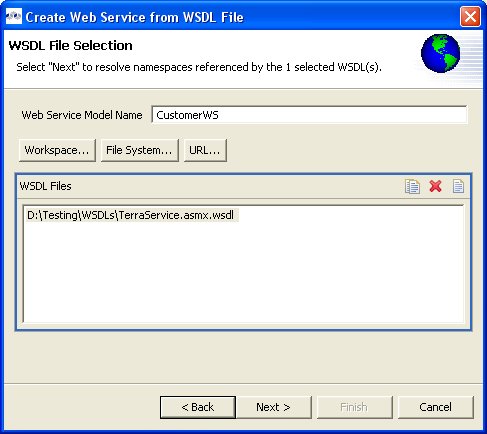
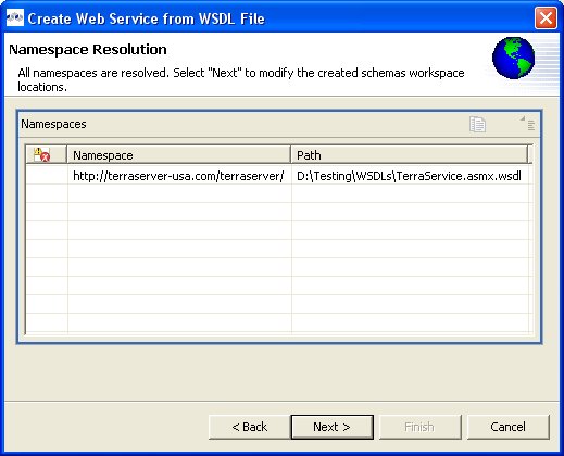
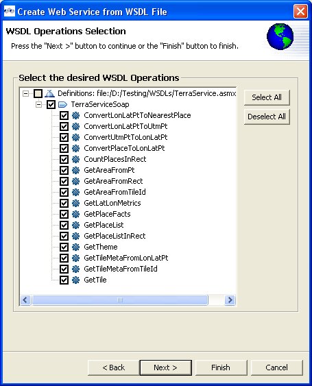
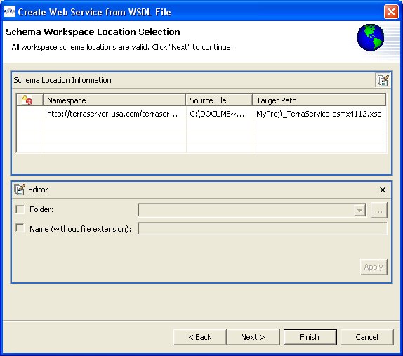
You can create a Web Service model by selecting a WSDL file based on a URL.
Step 1 - In Model Explorer choose the File > Import action
in the toolbar or select a project, folder or
model in the tree and choose Import...Step 2 - Select the import option Metadata Modeling > WSDL File into Web Service Model and click Next>
Step 3 - Input a valid name for your Web Service model and select the URL... button. Locate your file system WSDL file in the selection dialog and click OK>.
Note
If no WSDL is selected or specified then the importer will only create an empty Web Service model. No XML Schema or XML View models will be generated.
Any referenced files (WSDLs or schemas) must either be embedded in the WSDL file or exist on your file system.
Step 4 - The next page is titled Namespace Resolution. This page identifies successful and errant WSDL namespace resolution. The main WSDL document will essentially always be resolved, since the workspace file chooser is used to obtain the path. Problems will occur when the main WSDL file imports other WSDL files that cannot be resolved. If no errors, select Next to proceed, or Finish (if enabled) to complete with default options.
Step 5 - The next page WSDL Operations Selection allows customizing the resulting content of your Web Service model by selecting/deselecting various operations and interfaces in the following dialog.
Step 6 - The next page is titled Schema Workspace Location Selection. This page lists all schemas imported by the WSDL (along with any dependent schemas referenced within schemas) as well as schemas embedded in the WSDL and indicates whether or not they are resolvable. All resolved schemas will be created in a separate file and added to the workspace. The editor panel allows you to change the default file name of the new schema file(s).
If no errors, select Next to proceed, or Finish to complete with default option
Step 7 - The last page titled XML Model Generation allows you to change the name of the XML View model if the Generate virtual XML document model is checked. Input desired name or use the default name provide. Select Finish to complete.
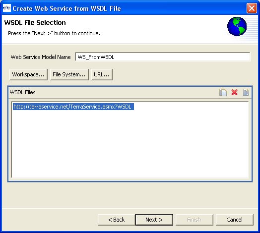
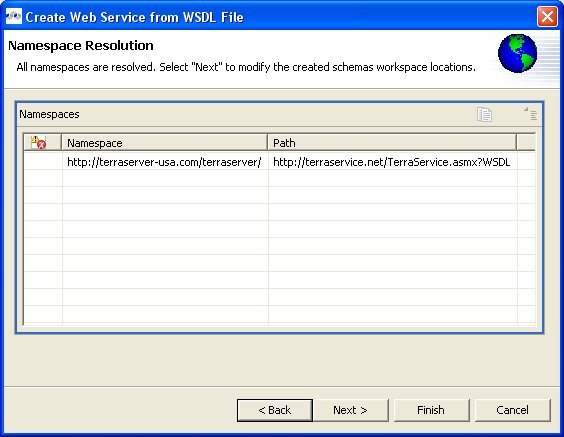
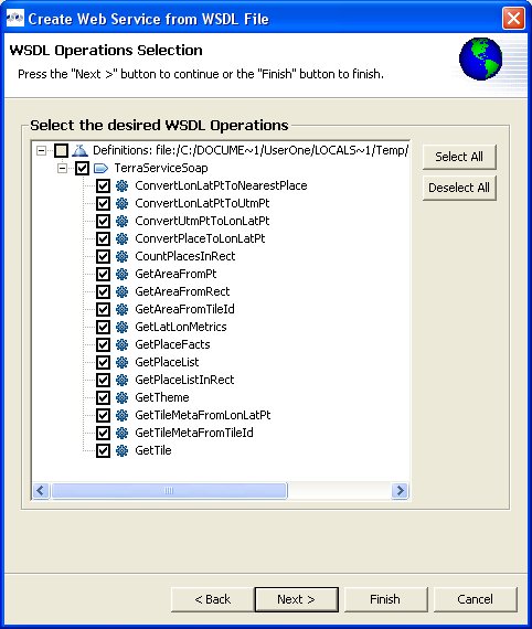
In addition to creating relational source models by importing your metadata you can also turn your existing XML Schema into relational source or view models. You can create XML View models using the steps below.
You can import files located on your local file system using the steps below.
Step 1 - Choose the File > Import action
in the toolbar or select a project, folder or
model in the tree and choose Import... to launch the
Import WizardStep 2 - Select the import option Metadata Modeling > XML Schema as Relational Source and click Next >
Step 3 - On the next page, specify all options for defining document source and catalog options then click Next >
Step 4 - On the XML Schema File Selection page, choose a schema file located in your Workspace... or a file on your local File System... . Click Next >
Step 5 - Select global elements that will be used as root elements in your XML documents and move them to the Document Root Elements list. Change any Mapping Options. Click Next >
Step 6 - Select or deselect schema elements to use in creating relational tables. Click Next >
Step 7 - Provide unique model name, model location (project or folder) and options. Click Finish
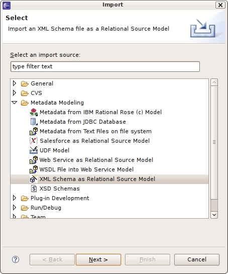
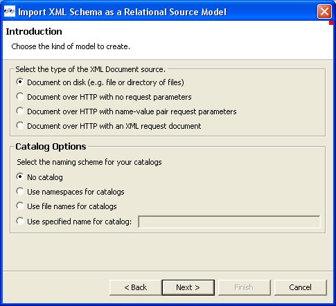
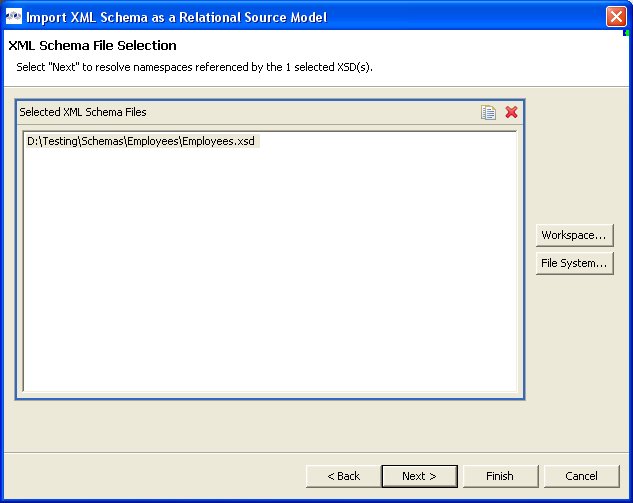
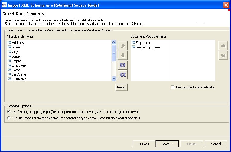
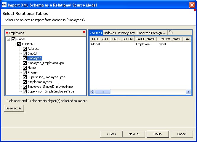
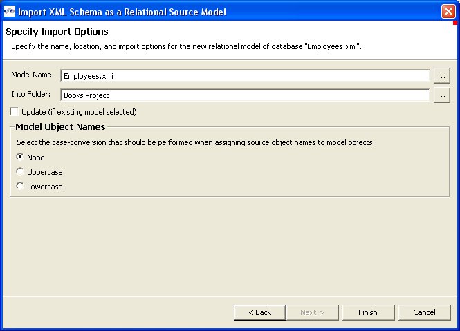
You can import XML Schema file (XSD) files using the steps below.
Step 1 - In Model Explorer choose the File > Import action
in the toolbar or select a project, folder or
model in the tree and choose Import...Step 2 - Select the import option Metadata Modeling > XSD Schema files on file system and click Next>
Step 3 - Select either Import XSD Schemas from file system or Import XSD Schemas via URL and click Next >
Step 4a - If importing from file system, the Import XSD Files dialog is displayed. Click on the Browse button to find the directory that contains the XSD file(s) you wish to import.
To select all of the XSD files in the directory, click the checkbox next to the folder in the left panel.
To select individual XSD files, click the checkboxes next to the files you want in the right panel
Step 4b - If importing from URL, enter valid XSD Schema URL and click OK to display the final Add XSD Schema URL's wizard page displaying the schemas available for import.
Step 5 - Click Finish.
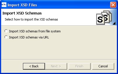
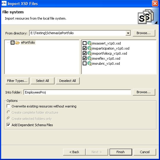
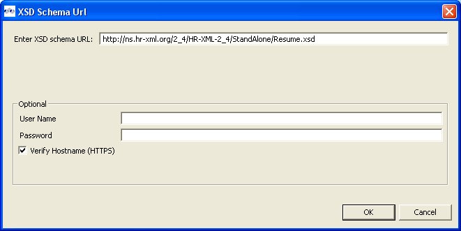
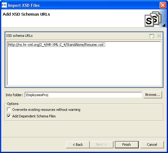
Note
XSD files may have dependent files. This importer will determine these dependencies and import these as well if Add Dependent Schema Files is checked
The Teiid Designer provides an option to an importer for files exported from Rational Rose versions 2000 and 2001.
The importer creates UML models in the workspace. Supported structural features of UML will be defined by the UMLClasses Metamodel Project. The content of the Rose model file that matches these supported features of the UML metamodel are imported.
The importer allows for subsequent re-importing of the Rose model file which will incorporate changes into the UML model. Any properties of the supported UML constructs that are unique to your use of Rose are implemented using the Teiid Designer's metadata extension functionality.
To import an Rose file, follow the steps below.
Step 1 - In Model Explorer choose the File > Import action
in the toolbar or select a project, folder or
model in the tree and choose Import...Step 2 - Select the import option Metadata Modeling > Metadata from IBM Rational Rose Model and click Next> to open the Rose model selection dialog.
Step 3 - Click on the
 button to locate and select your
IBM Rational Rose Model ( *.mdl or *.cat) file.
Check the appropriate models and/or model children to import. Click Next >
button to locate and select your
IBM Rational Rose Model ( *.mdl or *.cat) file.
Check the appropriate models and/or model children to import. Click Next >Step 4 - Select the target models and folders in editor panel and click Next > to display a target models and folders dialog. A progress monitor will display intermediate processing status.
Note
If preserving the file system structure of the source Rose Units being imported is desired, a similar file system structure must exist in the model target location prior to starting the wizard.
This wizard page consists of two distinct areas: the selected source Rose Units table and an Editor.
The table identifies the Rose Units being imported. For each Rose Unit a target folder and target model name is shown, as well as, an error or warning indicator. The initial value of the target folder will be set to the model project or folder that was selected prior to starting the wizard (or none if there was no previous selection). Selection buttons to the right of the table aid in selecting table rows. Values in the selected table rows are changed via the editor.
The Editor allows target folders and model names to be changed. The editor modifies all selected table rows (the top area) with its information once the Apply button is selected. If more than one row is selected, the information area shows only the common information.
For example, if two rows are selected that have the same target folder, then that target folder will show in the editor. However, if two rows are selected with different target folders, the editor will not show any information for the folder.
When changes are made in the editor, the appropriate checkbox is automatically checked. Unchecking the checkbox will reset the editor back to the original value. For both the target folder and target model properties, using their respective browse buttons can set new values. This allows navigation of the workspace. Selecting a recently used value in the drop-down dialog can also set new values. The editor can be closed and opened either by using the editor's toolbar button or the top areas toolbar button.
Step 5 - Selecting this import option gives you the opportunity to de-select specific UML model entity(s). All checked elements will be included in your UML model.
Step 6 - Click Finish.
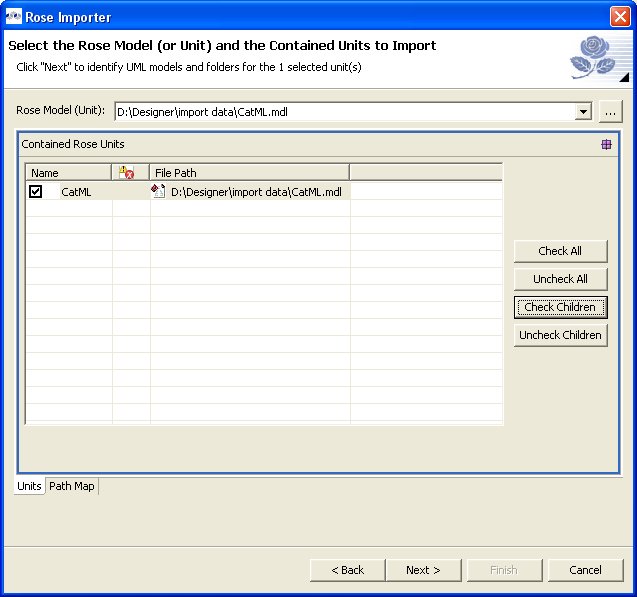
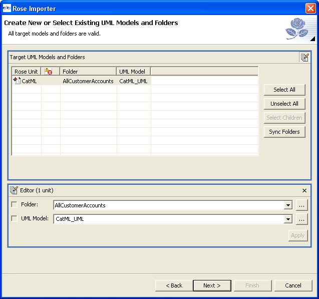
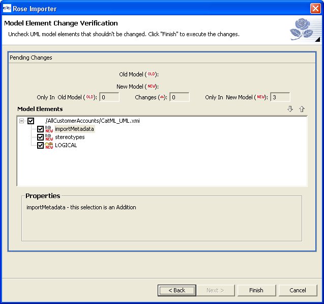
- 7.1. Creating New Relational Source Model
- 7.2. Creating New Relational View Model
- 7.3. Creating New XML Service Source Model
- 7.4. Creating New XML Service View Model
- 7.5. Creating XML Document View Model
- 7.6. Creating XML Schema Model
- 7.7. Creating Web Service View Model
- 7.8. Creating New Extensions Model
- 7.9. Creating New Relationship Model
- 7.10. Creating New UML 2.0 Model
Go To: Table of Contents
Models are the primary resource used by the Teiid Designer. Creating models can be accomplished by either directly importing existing metadata or by creating them using one of several New Model wizard options. This section describes these wizards in detail.
The Teiid Designer currently supports the following types of models:
Use one of the following options to launch the New Model Wizard.
Choose the File > New... > Metadata Model action
.
Select a project or folder in the Section 4.1, “Model Explorer View” and choose the same action in the right-click menu.
Select the New button on the main toolbar
 and select the
Metadata Model
action .
and select the
Metadata Model
action .
Note
Model names are required to be unique within Designer. When specifying model names in new model wizards and dialogs error messages will be presented and you will prevented from entering an existing name.
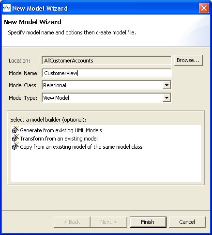
To create a new empty relational source model:
Step 1 - Launch the New Model wizard.
Step 2 - Specify a unique model name.
Step 3 - Select Relational option from Model Class drop-down menu.
Step 4 - Select Source Model from Model Type drop-down menu.
Step 5 - Click Finish.
Note
You can change the target location (i.e. project or folder) by selecting the Browse... button and selecting a project or folder within your workspace.
In addition to creating a new empty relational source model, the following builder options are available:
Copy from existing model of the same model class.
Generate from existing UML models.
This builder option performs a structural copy of the contents of an existing model to a newly defined model. You can choose a full copy or select individual model components for copy.
To create a new relational model by copying contents from another relational source model, complete steps 1 through 4 above and continue with these additional steps:
Step 5 - Select the model builder labeled Copy from existing model of the same model class and click Next >. The Copy Existing Model dialog will be displayed.
Step 6 - Select an existing relational model from the workspace using the browse button.
Note
An existing model will be pre-selected if a relational model in the workspace is selected in the Section 4.1, “Model Explorer View” prior to starting the new model wizard.
Step 7 - Check the Copy all descriptions option if desired. Click Finish
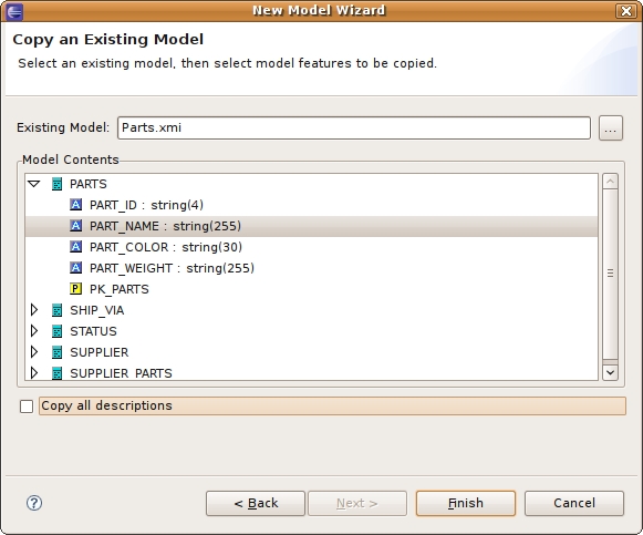
In the Teiid Designer you can also turn your existing UML models into relational source or view models using the steps below. Note that one option of this builder is to generate relationships between the UML constructs and their generated Relational counterparts.
To create a new relational model generated from an existing UML model, complete steps 1 through 4 above and continue with these additional steps:
Step 5 - Select the model builder labeled Generate from existing UML models and click Next >.
Step 6 - On the next page, select the UML model you wish to convert and check/uncheck desired contents, then click Next >.
Step 7 - On the next page select or create a relationship model to place your generated relationships in. If you do not wish to generate relationships, check the Do not create relationships to UML source entities option. When finished, click Next > or Finish to generate using default options.
Step 8 - The next page allows you to choose and customize various optional properties used in generating your relationship model entities. When finished with these options, click Next > or Finish to generate using default options.
Step 9 - The next page allows you to choose and customize various optional datatype properties used in generating your relationship model entities. When finished with these options, click Next > or Finish to generate using default options.
Step 10 - The next page allows you to choose and customize various optional properties used in generating your relationship model entities. When finished with these options, click Next > or Finish to generate using default options.
Step 11 - Click Finish.
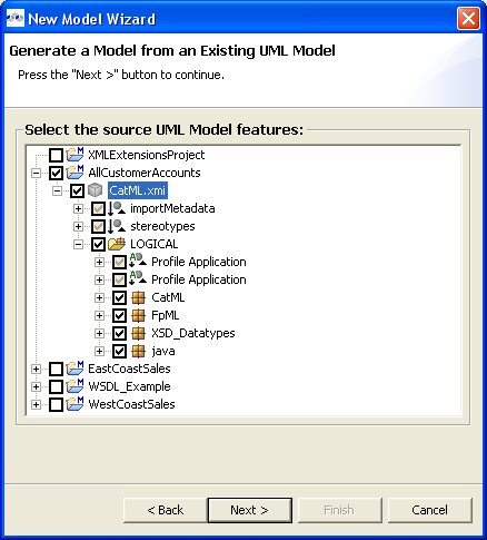
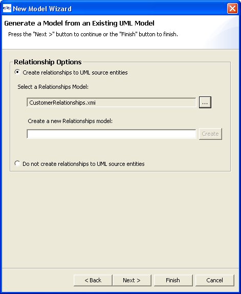
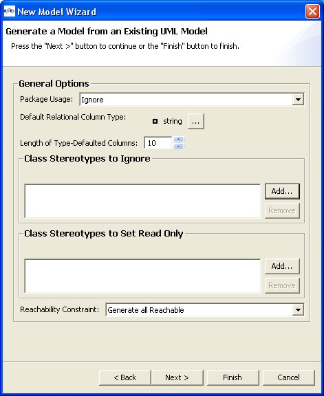
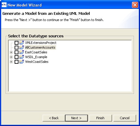
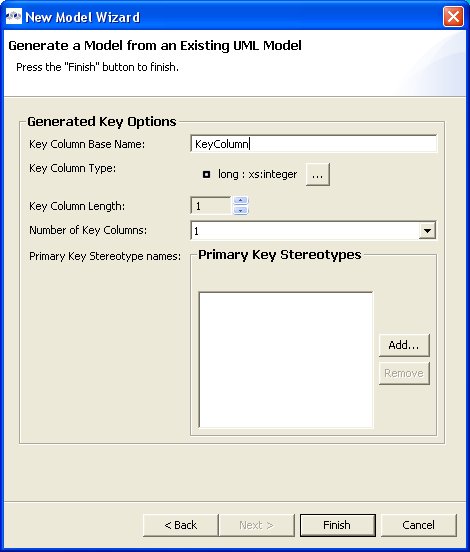
To create a new empty relational view model:
Step 1 - Launch the New Model wizard.
Step 2 - Specify a unique model name.
Step 3 - Select Relational option from Model Class drop-down menu.
Step 4 - Select View Model from Model Type drop-down menu.
Step 5 - Click Finish.
Note
You can change the target location (i.e. project or folder) by selecting the Browse... button and selecting a project or folder within your workspace.
In addition to creating a new empty relational view model, the following builder options are available:
Copy from existing model of the same model class.
Transform from existing model.
Generate from existing UML models.
This builder option performs a structural copy of the contents of an existing model to a newly defined model. You can choose a full copy or select individual model components for copy.
To create a new relational model by copying contents from another relational view model, complete steps 1 through 4 above and continue with these additional steps:
Step 5 - Select the model builder labeled Copy from existing model of the same model class and click Next >. The Copy Existing Model dialog will be displayed.
Step 6 - Select an existing relational model from the workspace using the browse button.
Step 7 - Check the Copy all descriptions option if desired. Click Finish
This option is only applicable for creating a relational view model from a relational source model with the added feature of creating default transformations (SELECT * FROM SourceModel.Table_X) for each source table. The steps are the same as for the Copy Model From Existing Model described above.
There is an additional option in the second page of the wizard which can automatically set the relational table's supports update property to false. If this is unchecked the default value will be true.
In the Teiid Designer you can also turn your existing UML models into relational source or view models. Creating a relational view model utilizes the same steps as for relational source models with the one change of setting Model Type to View Model instead of Source Model.
In the Teiid Designer you can use your existing schema models to generate relational view tables.
To create a new relational view model from XML schema:
Step 1 - Select any XML Schema model (XSD) in in the Section 4.1, “Model Explorer View” tree.
Step 2 - Right-click to display the context menu and select the Modeling > Create Relational View Model from Schema action.
Step 3 - In the Create Virtual Tables from XSD Schema Wizard dialog, specify a relational view model name.
Step 4 - Select one or more global schema entities and move from left panel to the right panel. Click Finish when done.
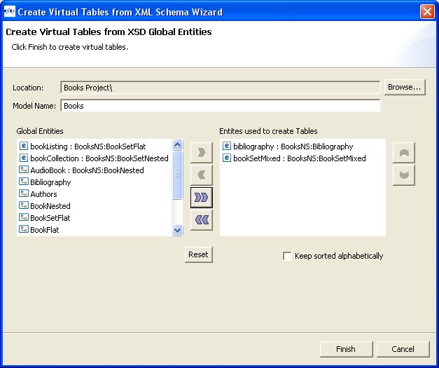
When model generation is complete the new model will be opened in an editor for your viewing.
To create a new empty xml service source model:
Step 1 - Launch the New Model wizard.
Step 2 - Specify a unique model name.
Step 3 - Select XML Service option from Model Class drop-down menu.
Step 4 - Select Source Model from Model Type drop-down menu.
Step 5 - Click Finish.
Note
You can change the target location (i.e. project or folder) by selecting the Browse... button and selecting a project or folder within your workspace.
In addition to creating a new empty xml service source model, the following builder option is available:
Copy from existing model of the same model class.
This builder option performs a structural copy of the contents of an existing model to a newly defined model. You can choose a full copy or select individual model components for copy.
To create a new relational model by copying contents from another xml service source model, complete steps 1 through 4 above and continue with these additional steps:
Step 5 - Select the model builder labeled Copy from existing model of the same model class and click Next >. The Copy Existing Model dialog will be displayed.
Step 6 - Select an existing relational model from the workspace using the browse button.
Step 7 - Check the Copy all descriptions option if desired. Click Finish
To create a new empty xml service view model:
Step 1 - Launch the New Model wizard.
Step 2 - Specify a unique model name.
Step 3 - Select XML Service option from Model Class drop-down menu.
Step 4 - Select View Model from Model Type drop-down menu.
Step 5 - Click Finish.
Note
You can change the target location (i.e. project or folder) by selecting the Browse... button and selecting a project or folder within your workspace.
In addition to creating a new empty xml service view model, the following builder option is available:
Copy from existing model of the same model class.
This builder option performs a structural copy of the contents of an existing model to a newly defined model. You can choose a full copy or select individual model components for copy.
To create a new relational model by copying contents from another xml service view model, complete steps 1 through 4 above and continue with these additional steps:
Step 5 - Select the model builder labeled Copy from existing model of the same model class and click Next >. The Copy Existing Model dialog will be displayed.
Step 6 - Select an existing relational model from the workspace using the browse button.
Step 7 - Check the Copy all descriptions option if desired. Click Finish
To create a new empty xml document view model:
Step 1 - Launch the New Model wizard.
Step 2 - Specify a unique model name.
Step 3 - Select XML option from Model Class drop-down menu.
Step 4 - Select View Model from Model Type drop-down menu.
Step 5 - Click Finish.
Note
You can change the target location (i.e. project or folder) by selecting the Browse... button and selecting a project or folder within your workspace.
In addition to creating a new empty xml document view model, the following builder options are available:
Copy from existing model of the same model class.
Build XML documents from XML schema.
This builder option performs a structural copy of the contents of an existing model to a newly defined model. You can choose a full copy or select individual model components for copy.
To create a new relational model by copying contents from another xml document view model, complete steps 1 through 4 above and continue with these additional steps:
Step 5 - Select the model builder labeled Copy from existing model of the same model class and click Next >. The Copy Existing Model dialog will be displayed.
Step 6 - Select an existing relational model from the workspace using the browse button.
Step 7 - Check the Copy all descriptions option if desired. Click Finish
This option creates an XML View document model based on a selected XML schema and its dependencies.
To create a new xml document view model by from XML schema, complete steps 1 through 4 above and continue with these additional steps:
Step 5 - Select the model builder labeled Build XML documents from XML schema and click Next >. The Select XML Schema dialog will be displayed.
Step 6 - Select an existing schema model from the workspace using the browse button.
Note
An existing model will be pre-selected if an XSD model in the workspace is selected in the VDB explorer prior to starting the new model wizard. The schema must be found in the workspace so if you need to get one or more into the workspace use the XSD Schemas on file system importer.
Step 7 - Move the available schema root elements you want to become virtual documents in the new model over to the Virtual Documents list by using the arrow button
 for selected elements or the
  button to move all elements.
Step 8 - Select the appropriate document options and mapping options. Click Finish
Step 9 - Click Finish to create a model of all selected document entities or (optional) click Next > to view Selected Documents Statistics page which shows document entity statistics and gives you an idea the size of the model being created.
Step 10 - (Optional) Click Finish to create a model of all selected document entities or click Next > to view Preview Generated Documents page that allows you to exclude document specific entities then click Finish.
Note
For deeply nested schema, your total entity count may be large. If so, displaying the preview may take some time.
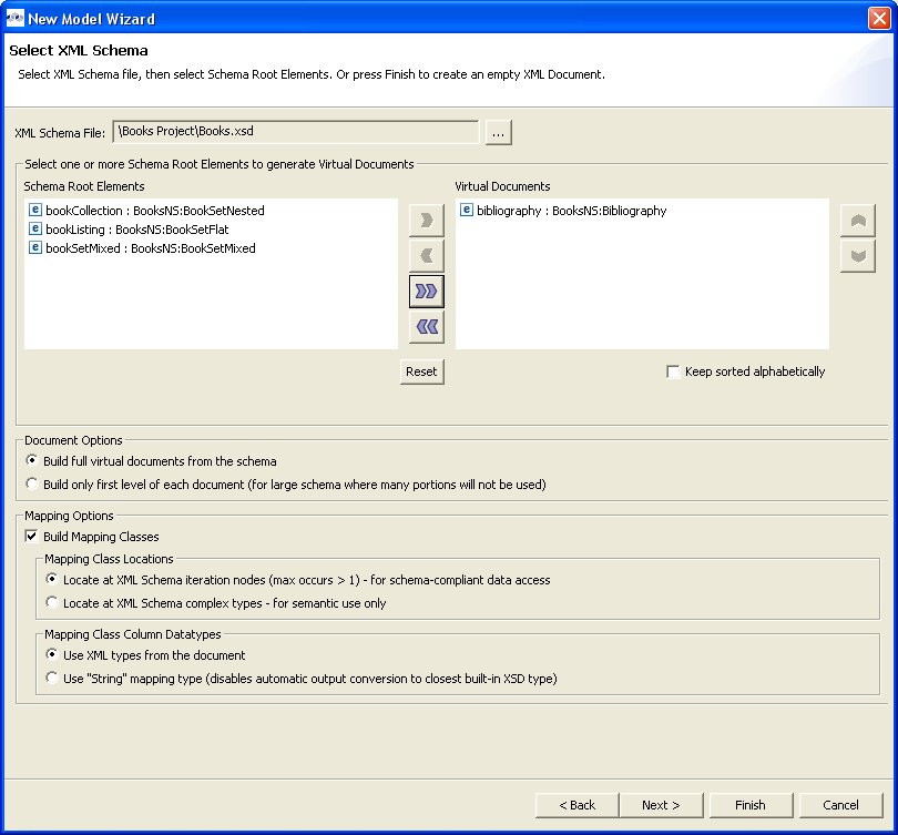
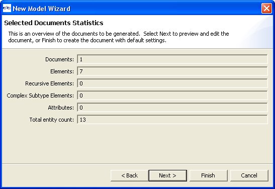
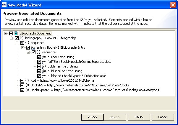
To create a new empty xml schema (.xsd) model:
Step 1 - Launch the New Model wizard.
Step 2 - Specify a unique model name.
Step 3 - Select XML Schema (XSD) option from Model Class drop-down menu.
Step 4 - Select Datatype Model from Model Type drop-down menu.
Step 5 - Click Finish.
Note
You can change the target location (i.e. project or folder) by selecting the Browse... button and selecting a project or folder within your workspace.
In addition to creating a new empty xml schema model, the following builder option is available:
Copy from existing model of the same model class.
This builder option performs a structural copy of the contents of an existing model to a newly defined model. You can choose a full copy or select individual model components for copy.
To create a new relational model by copying contents from another xml schema model, complete steps 1 through 4 above and continue with these additional steps:
Step 5 - Select the model builder labeled Copy from existing model of the same model class and click Next >. The Copy Existing Model dialog will be displayed.
Step 6 - Select an existing relational model from the workspace using the browse button.
Step 7 - Check the Copy all descriptions option if desired. Click Finish
To create a new empty web service view model:
Step 1 - Launch the New Model wizard.
Step 2 - Specify a unique model name.
Step 3 - Select Web Service option from Model Class drop-down menu.
Step 4 - Select View Model from Model Type drop-down menu.
Step 5 - Click Finish.
Note
You can change the target location (i.e. project or folder) by selecting the Browse... button and selecting a project or folder within your workspace.
In addition to creating a new empty web service view model, the following builder options are available:
Copy from existing model of the same model class.
Build from existing WSDL file(s) or URL.
This builder option performs a structural copy of the contents of an existing model to a newly defined model. You can choose a full copy or select individual model components for copy.
To create a new relational model by copying contents from another web service view model, complete steps 1 through 4 above and continue with these additional steps:
Step 5 - Select the model builder labeled Copy from existing model of the same model class and click Next >. The Copy Existing Model dialog will be displayed.
Step 6 - Select an existing relational model from the workspace using the browse button.
Step 7 - Check the Copy all descriptions option if desired. Click Finish
This builder option creates a Web service model based on a user-defined WSDL file and its referenced schemas. In addition, applicable XML schema files and XML View document models (optional) are created.
To create a new relational model by copying contents from another web service view model, complete steps 1 through 4 above and continue with these additional steps:
Step 5 - Select the model builder labeled Build from existing WSDL file(s) or URL and click Next >.
The remaining wizard steps are identical to those found using the Import > WSDL File into Web Service Model action option.
This method is recommended for experienced users for consistent and rapid deployment of Web services designed to query relational sources. It provides detailed control of all Web service interfaces, operations and required transformations from XML Views
To create a Web service model from relational models or objects:
Step 1 - Select any combination of relational models, tables and/or procedures in the Section 4.1, “Model Explorer View” tree..
Note
It is recommended that the user selects single source models, which enables auto-naming of input/output schema and Web service models in \ Step 3.
Step 2 - Right-click select Modeling > Create Web Service action
 .
.Step 3 - In the Create Web Service dialog, specify file names for the generated Input Schema file, Output Schema file and Web service model. Change options as desired. Click Finish when done.
Step 4 - When model generation is complete, a confirmation dialog should appear. Click OK.
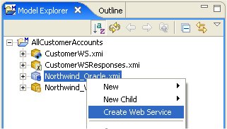
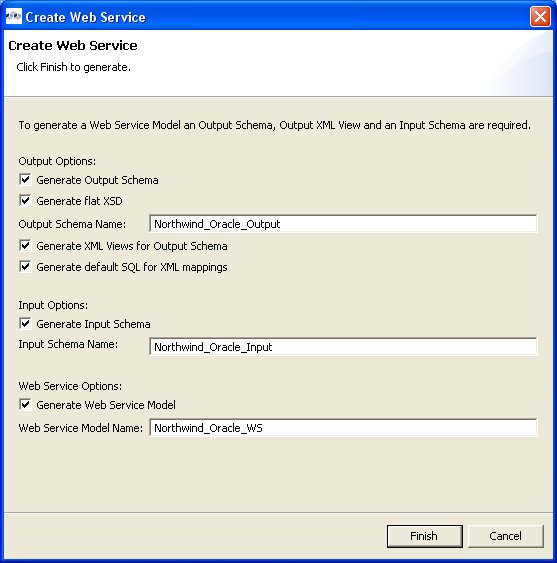
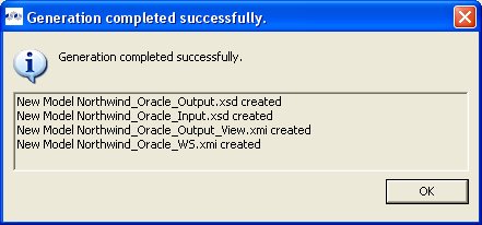
Web Service models and their corresponding Interfaces and Operations can be generated in Teiid Designer from XML View model components. Namely, XML View Documents and XML View Document roots.
To create a new Web service model from XML components::
Step 1 - Select either a single XML Document or single XML Document root in Section 4.1, “Model Explorer View”.
Step 2 - Right-click select Modeling > Create Web Service action
.Step 3 - Fill in missing properties in Web Service Generation Wizard shown below.
Step 4 - Click Finish to generate model. When model generation is complete, a confirmation dialog should appear. Click OK.
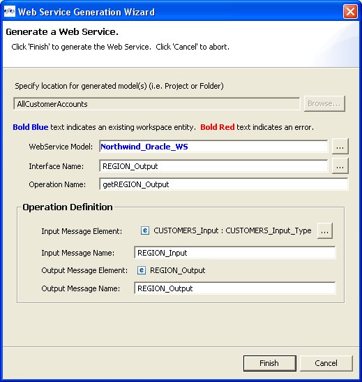
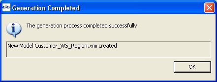
Note
Users can change the Web Service Model and Interface Name values (via "..." buttons) to use existing Web service model components. This will create a new operation in an existing model.
To create a new empty extensions model:
Step 1 - Launch the New Model wizard.
Step 2 - Specify a unique model name.
Step 3 - Select Model Extensions option from Model Class drop-down menu.
Step 4 - Select Model Class Extension from Model Type drop-down menu.
Step 5 - Click Finish.
Note
You can change the target location (i.e. project or folder) by selecting the Browse... button and selecting a project or folder within your workspace.
In addition to creating a new empty extensions model, the following builder option is available:
Copy from existing model of the same model class.
This builder option performs a structural copy of the contents of an existing model to a newly defined model. You can choose a full copy or select individual model components for copy.
To create a new relational model by copying contents from another extensions model, complete steps 1 through 4 above and continue with these additional steps:
Step 5 - Select the model builder labeled Copy from existing model of the same model class and click Next >. The Copy Existing Model dialog will be displayed.
Step 6 - Select an existing relational model from the workspace using the browse button.
Step 7 - Check the Copy all descriptions option if desired. Click Finish
To create a new empty relationships model:
Step 1 - Launch the New Model wizard.
Step 2 - Specify a unique model name.
Step 3 - Select Relationship option from Model Class drop-down menu.
Step 4 - Select Logical Model from Model Type drop-down menu.
Step 5 - Click Finish.
Note
You can change the target location (i.e. project or folder) by selecting the Browse... button and selecting a project or folder within your workspace.
In addition to creating a new empty relationship model, the following builder option is available:
Copy from existing model of the same model class.
This builder option performs a structural copy of the contents of an existing model to a newly defined model. You can choose a full copy or select individual model components for copy.
To create a new relational model by copying contents from another relationships model, complete steps 1 through 4 above and continue with these additional steps:
Step 5 - Select the model builder labeled Copy from existing model of the same model class and click Next >. The Copy Existing Model dialog will be displayed.
Step 6 - Select an existing relational model from the workspace using the browse button.
Step 7a - If Copy entire model option is selected, Click Finish
Step 7b - If Select Model Features to Copy option is selected, select and/or de-select desired model objects to be included or excluded from the structural copy and click Finish.
To create a new empty UML 2.0 model:
Step 1 - Launch the New Model wizard.
Step 2 - Specify a unique model name.
Step 3 - Select UML 2.0 option from Model Class drop-down menu.
Step 4 - Select Logical Model from Model Type drop-down menu.
Step 5 - Click Finish.
Note
You can change the target location (i.e. project or folder) by selecting the Browse... button and selecting a project or folder within your workspace.
In addition to creating a new empty uml model, the following builder option is available:
Copy from existing model of the same model class.
This builder option performs a structural copy of the contents of an existing model to a newly defined model. You can choose a full copy or select individual model components for copy.
To create a new relational model by copying contents from another UML model, complete steps 1 through 4 above and continue with these additional steps:
Step 5 - Select the model builder labeled Copy from existing model of the same model class and click Next >. The Copy Existing Model dialog will be displayed.
Step 6 - Select an existing relational model from the workspace using the browse button.
Step 7 - Check the Copy all descriptions option if desired. Click Finish
Go To: Table of Contents
This section summarizes Teiid Designer features for creating and editing existing model objects contained in your models.
As discussed in the introduction, Metadata Models provide a framework to model various types of metadata. Each metamodel type has a set of parent-child relationships that establish constraints on what can be created and where. You cannot, for example, create a column attribute in a stored procedure, nor can you create a mapping class column in a Web service operation's output message.
The Teiid Designer provides a common set of actions to create new children of these models as well as children of children.
You can create new model objects directly in the Section 4.1, “Model Explorer View” view, Diagram Editor or Table Editor using the following actions:
New Child Action
New Sibling Action
New Association Action
To create new child model objects in the Section 4.1, “Model Explorer View”:
Step 1 - Select the parent object to which you want to add a child. For example, you can add a package to a package or an attribute to a class.
Step 2 - Right-click on a container object. From the pop-up menu, select New Child. You can now select the child object you would like to add.
Step 3 - The new model object displays on the Section 4.1, “Model Explorer View” and is highlighted for renaming.
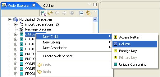
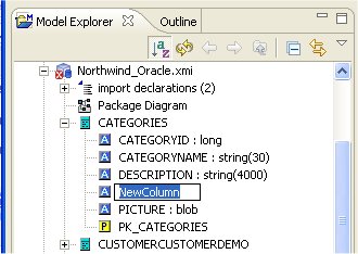
To create new child model objects in the Diagram Editor:
Step 1 - Select the parent object to which you want to add a child. For example, you can add a package to a package or an attribute to a class.
Step 2 - Right-click on a container object. From the pop-up menu, select New Child. You can now select the child object you would like to add.
Step 3 - The new model object displays on the diagram and is highlighted for renaming.
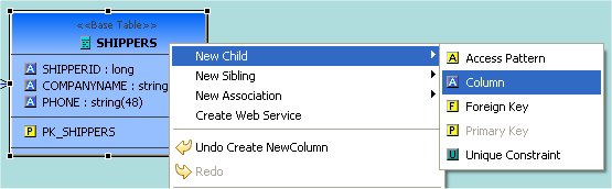
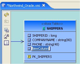
To create new child model objects in the Table Editor:
Step 1 - Select the row for the parent object to which you want to add a child. For example to add a column, click the Base Table tab and select base table row.
Step 2 - Right-click on a table row. From the pop-up menu, select New Child. You can now select the child object you would like to add.
Step 3 - The selected tab in the Table Editor changes to the tab for the child object type, the new model object row is displayed and the row's name table cell is highlighted for renaming.
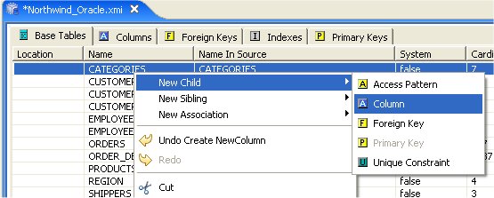
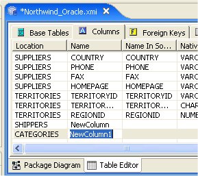
To create new sibling model objects in the Section 4.1, “Model Explorer View”:
Step 1 - Select the object to which you want to add a sibling. For example, you can add a column sibling to a column.
Step 2 - Right-click on that object. From the pop-up menu, select New Sibling. You can now select the sibling object you would like to add.
Step 3 - The new model object displays on the Section 4.1, “Model Explorer View” and is highlighted for renaming.
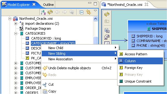
To create new sibling model objects in the Diagram Editor:
Step 1 - Select the object to which you want to add a sibling. For example, you can add a column sibling to a column.
Step 2 - Right-click on that object. From the pop-up menu, select New Sibling. You can now select the sibling object you would like to add.
Step 3 - The new model object displays on the diagram and is highlighted for renaming.
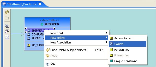
To create new sibling model objects in the Table Editor:
Step 1 - Select the row for the object to which you want to add a sibling. For example, you can add a column sibling to a column.
Step 2 - Right-click on a row. From the pop-up menu, select New Sibling. You can now select the sibling object you would like to add.
Step 3 - The selected tab in the Table Editor changes to the tab for the child object type, the new model object row is displayed and the row's name table cell is highlighted for renaming.
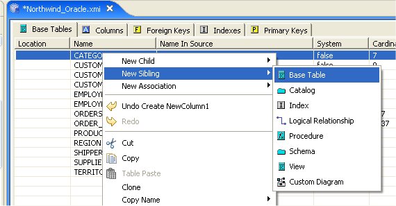
To create new associations between model objects in the Section 4.1, “Model Explorer View”:
Step 1 - Select two objects you wish to associate. For example, select columns in different base tables.
Step 2 - Right-click. From the pop-up menu, select New Association > Foreign Key Relationship..
Step 3 - The new relationship link is displayed in the diagram.
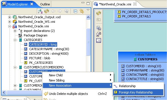
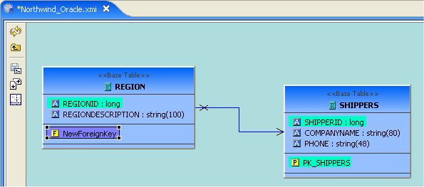
To create new associations between model objects in the Diagram Editor:
Step 1 - Select two objects you wish to associate. For example, select columns in different base tables.
Step 2 - Right-click. From the pop-up menu, select New Association > Foreign Key Relationship..
Step 3 - The new relationship link is displayed in the diagram. The Column, Foreign Key, Primary Key reference properties are properly set on the selected columns, new primary key and new foreign key.
OR
Step 1 - Select a column in table.
Step 2 - Drag the column to another table and drag over a column and drop onto this column. The target column should highlight in Yellow.
Step 3 - The new relationship link is displayed in the diagram. The Column, Foreign Key, Primary Key reference properties are properly set on the selected columns, new primary key and new foreign key.
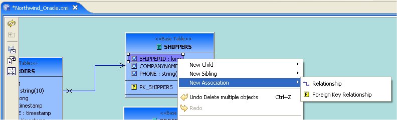
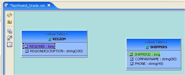
To create new associations between model objects in the Table Editor:
Step 1 - Select two objects you wish to associate. For example, select columns in different base tables.
Step 2 - Right-click. From the pop-up menu, select New Association > Foreign Key Relationship..
Step 3 - New Foreign Key and Primary Key objects will be added to the contents of their respective tabs in the Table Editor. The Column, Foreign Key, Primary Key reference properties are properly set on the selected columns, new primary key and new foreign key.

Teiid Designer provides specialized object editors to handle complex model objects and their unique properties. These objects include:
This section describes these editors in detail.
In addition, the primary actions for editing model objects are:
- Cut - Deletes the selected object(s) and copies it to the clipboard.
- Copy - Copies the selected object(s) to the clipboard.
- Paste - Pastes the contents of the clipboard to the selected context.
Clone - Duplicates the selected object in the same location with the same name; user is able to rename the new object right in the tree.
- Delete - Deletes the selected object(s).
Rename - Allows a user to rename an object.
These actions are presented in Teiid Designer's main Edit menu and also in the right-click context menus for model objects selected in the Model Explorer, Diagram Editor and Table Editor.
The Teiid Designer's Transformation Editor enables you to create the query transformations that describe how to derive your virtual metadata information from physical metadata sources or other virtual metadata and how to update the sources.
The Transformation Editor provides a robust set of tools you can use to create these SQL queries. You can use these tools, or you can simply type a SQL query into the Transformation Editor.
To edit a transformation you can:
Double-click Edit
A relational view table or procedure in the Model Explorer or Diagram Editor
A transformation node in a transformation diagram or mapping transformation diagram
A mapping class in a mapping diagram or mapping transformation diagram
Right-click Edit action on selected object in the Model Explorer, Diagram Editor or Table Editor
A relational view table or procedure
A transformation node in a transformation diagram or mapping transformation diagram
A mapping class in a mapping diagram or mapping transformation diagram
If a Model Editor is not currently open for the selected object's model, a Model Editor will be opened.
After the corresponding transformation diagram is opened in the Diagram Editor, the Transformation Editor is displayed in the lower section of the Diagram Editor.
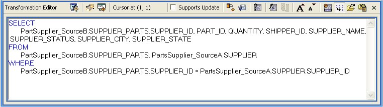
If this virtual class supports updates, the tabs on the bottom of the Transformation Editor allow you to enter SQL for each type of query this virtual class supports. If this virtual class does not support updates, only the SELECT tab is available.
You can enter separate SQL queries on each available tab to accommodate that type of query.
Within the Transformation Editor, you can:
Disable specific update transformation types on this virtual class.
Build or edit a criteria clause to use in your transformation.
Build or edit an expression to use in your transformation.
Find and replace a string within your transformation.
Validate the transformation to ensure its content contains no errors.
Reconcile target attributes to ensure the symbols in your transformation match the attributes in your virtual metadata class.
You can also set preferences that impact the display of your Transformation Editor. For more information, see Transformation Editor Preferences.
The Transformation Editor toolbar actions are summarized below.
 Prevew Virtual Data - executes a simple
preview query for the target table or procedure of the transformation being edited.
Prevew Virtual Data - executes a simple
preview query for the target table or procedure of the transformation being edited.
- Search Transformations - provides a simple
way select and edit another transformation based SQL text search criteria.
 Edit Transformation - provides a simple way
to change which transformation to edit without searching in a diagram or the Model Explorer.
Simply click the action and select from a list of views, tables, procedures or operations from
the currently edited model.
Edit Transformation - provides a simple way
to change which transformation to edit without searching in a diagram or the Model Explorer.
Simply click the action and select from a list of views, tables, procedures or operations from
the currently edited model.
 Cursor Position (line, column) - shows the
current line and column position of the insertion cursor. For example, Cursor Position(1,4)
indicates that the cursor is presently located at column 4 of line 1.
Cursor Position (line, column) - shows the
current line and column position of the insertion cursor. For example, Cursor Position(1,4)
indicates that the cursor is presently located at column 4 of line 1.
 Supports Update - checkbox allows you to
enable or disable updates for the current transformation target. If 'Supports Update' is checked,
the editor shows four tabs at the bottom for the Select, Update, Insert and Delete transformations.
If 'Supports Update' is unchecked, all updates are disabled and only the Select transformation is
displayed.
Supports Update - checkbox allows you to
enable or disable updates for the current transformation target. If 'Supports Update' is checked,
the editor shows four tabs at the bottom for the Select, Update, Insert and Delete transformations.
If 'Supports Update' is unchecked, all updates are disabled and only the Select transformation is
displayed.
- Reconcile - allows you to resolve any
discrepancies between the transformation symbols and the target attributes. Pressing this button
will display the "Reconcile Virtual Target Attributes" dialog box in which you can resolve
discrepancies.
 Save/Validate - saves edits to the current
transformation and validates the transformation SQL. Any Warning or Error messages will be
displayed at the bottom of the editor in the messages area. If the SQL validates without error,
the message area is not displayed.
Save/Validate - saves edits to the current
transformation and validates the transformation SQL. Any Warning or Error messages will be
displayed at the bottom of the editor in the messages area. If the SQL validates without error,
the message area is not displayed.
 Criteria Builder - allows you to build a
criteria clause in your transformation. The button will enable if the cursor position is within
a query that allows a criteria. Pressing the button will launch the Criteria Builder dialog. If
the Criteria Builder is launched inside an existing criteria, that criteria will be displayed for
edit, otherwise the Criteria Builder will be initially empty.
Criteria Builder - allows you to build a
criteria clause in your transformation. The button will enable if the cursor position is within
a query that allows a criteria. Pressing the button will launch the Criteria Builder dialog. If
the Criteria Builder is launched inside an existing criteria, that criteria will be displayed for
edit, otherwise the Criteria Builder will be initially empty.
 Expression Builder - allows you to build an
expression within your transformation. The button will enable if the cursor position is at a
location that allows an expression. Pressing the button will launch the Expression Builder dialog.
If the Expression Builder is launched inside an existing expression, that expression will be
displayed for edit, otherwise the Expression Builder will be initially empty.
Expression Builder - allows you to build an
expression within your transformation. The button will enable if the cursor position is at a
location that allows an expression. Pressing the button will launch the Expression Builder dialog.
If the Expression Builder is launched inside an existing expression, that expression will be
displayed for edit, otherwise the Expression Builder will be initially empty.
 Expand Select * - allows you to expand a
"SELECT *" clause into a SELECT clause which contains all of the SELECT symbols. The button will
enable only if the cursor is within a query that contains a SELECT * clause that can be expanded.
Expand Select * - allows you to expand a
"SELECT *" clause into a SELECT clause which contains all of the SELECT symbols. The button will
enable only if the cursor is within a query that contains a SELECT * clause that can be expanded.
 Increase Font Size - increases the font size
of all editor text by 1.
Increase Font Size - increases the font size
of all editor text by 1.
 Decrease Font Size - decreases the font size
of all editor text by 1.
Decrease Font Size - decreases the font size
of all editor text by 1.
 Show/Hide Messages - toggles the display of
the message area at the bottom of the transformation editor.
Show/Hide Messages - toggles the display of
the message area at the bottom of the transformation editor.
 Optimize SQL - when toggled 'ON', will use
the short names of all SQL symbols that can be optimized. Some symbol names may remain fully
qualified in the event of a duplicate name or if the optimizer is unable to optimize it. When the
action is toggled 'OFF', all symbol names will be fully-qualified.
Optimize SQL - when toggled 'ON', will use
the short names of all SQL symbols that can be optimized. Some symbol names may remain fully
qualified in the event of a duplicate name or if the optimizer is unable to optimize it. When the
action is toggled 'OFF', all symbol names will be fully-qualified.
 Import SQL Text - allows you to import a sql
statement from a text file on your file system. Pressing this button will display an import dialog
in which you can navigate to the file.
Import SQL Text - allows you to import a sql
statement from a text file on your file system. Pressing this button will display an import dialog
in which you can navigate to the file.
 Export SQL Text - allows you to export the
currently displayed sql statement into a text file on your file system.
Pressing this button will display an export dialog in which you can choose the location for export.
Export SQL Text - allows you to export the
currently displayed sql statement into a text file on your file system.
Pressing this button will display an export dialog in which you can choose the location for export.
Close "X" - closes the transformation editor.
The Transformation Editor’s Criteria Builder offers you a quick, graphical means to build criteria clauses in your transformations based on meta objects in your diagram. If you launch the Criteria Builder with your cursor within an existing criteria in your transformation SQL, the builder will open in Edit mode. If your cursor is not in an existing criteria location, the builder will open in create mode and allow you to create it from scratch.
This procedure provides an example of building a criteria clause using the Criteria Builder. When building your own criteria, you can mix and match the values and constants with whatever logic you need to build powerful and complex criteria.
To use the Criteria Builder:
Step 1 - In the Transformation Editor, click the Launch Criteria Builder button.
Step 2 - The Criteria Builder displays.
The two tabs at the top, Tree View and SQL View, show the current contents of the criteria you have built.
The Criteria Editor at the bottom allows you to build a criteria clause. To build a criteria clause, you must add information to the left side of the predicate, select a comparison operator, and add a value to the right side.
Step 3 - The radio buttons on either side of the Predicate Editor let you choose what type of content to place in that side of your predicate. Click the radio button of the type of content you want to place in your criteria. You can click:
Attribute to add an attribute to the predicate. If you click the Attribute radio button, the Predicate Editor looks like this:
From the tree, select the attribute you want to add to the expression. You can select an attribute from any of the source classes in the transformation.
Constant to add a hard-wired constant value to the predicate. If you click this radio button, the Predicate Editor looks like this:
Select the datatype for this constant from the Type drop-down list and enter the value in the Value edit box.
Function to add a function. If you click the Function radio button, the Predicate Editor looks like this:
Click the Edit button to use the Expression Builder to construct a function to use in the predicate of your SQL Criterion. For more information about the Expression Builder, see “Using the Expression Builder.”
Step 4 - Set a value left side of the predicate and, when necessary, the right side of the predicate. If the right side of the predicate does not require a value of some sort, the Criteria Builder will not let you enter one.
Step 5 - Click Apply.
Step 6 - When you have created both a Left Expression and a Right Expression in the Predicate Editor, click Apply to add the criterion to the tree view at the top of the dialog box.
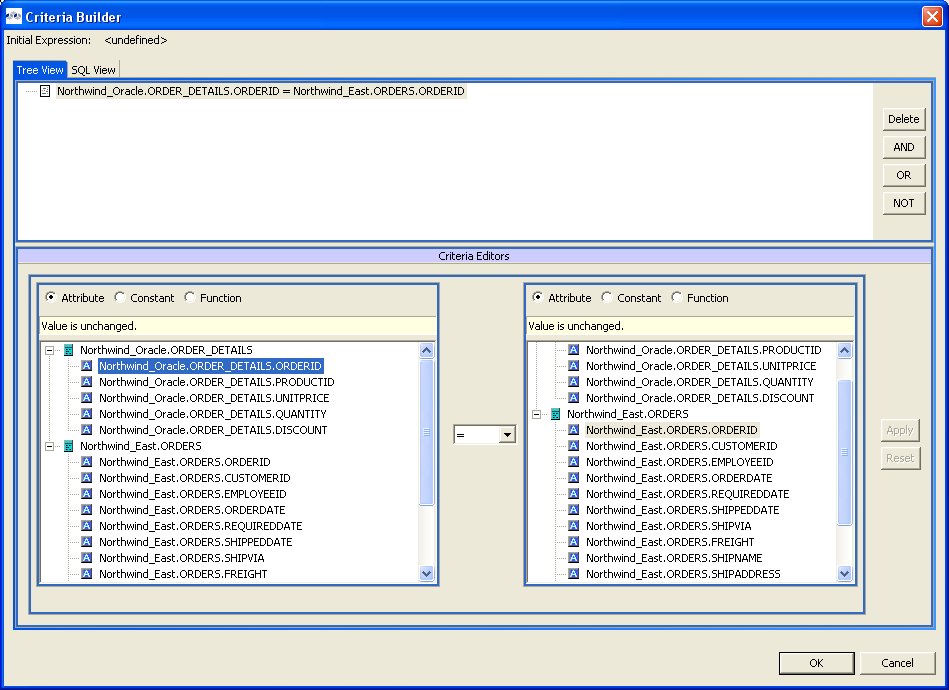
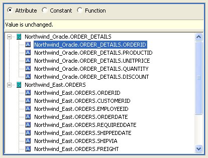
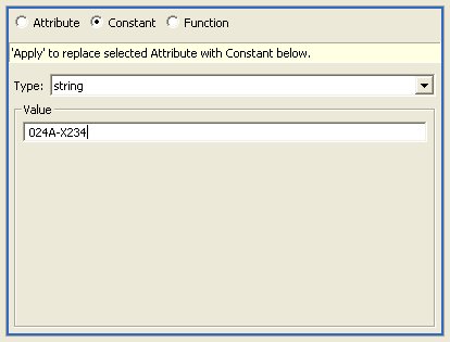
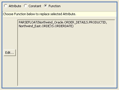
The criteria clause displays in the Criteria tree.
You can create complex criteria by joining other criteria with this one. To join criteria with this one, select the criteria in the Criteria tree and click:
Delete to remove the selected criterion.
AND to create a new criterion that must also be true.
OR to create a new criterion that can be true instead of the selected criterion.
NOT to establish negative criterion.
If you join a criterion to the one you just completed, you build the expression the same way, using the Expression Editors panel and the Predicate Editor panel. You can create complex, nested criteria by judicious use of the AND and OR buttons.
Once you have created the complete criteria you want, click OK to add it to your transformation.
The Transformation Editor’s Expression Builder offers you a quick, graphical means to build expressions in your transformations. This Expression Builder lets you create:
Attributes by selecting an attribute.
Constants by selecting the datatype and value.
Functions from both the standard Teiid Designer SQL functions and your enterprise’s custom user-defined functions. If you select a function before you launch the Expression Builder, you can use the Expression Builder to edit the selected function; otherwise, you can create a new function from scratch.
To use the Expression Builder:
Step 1 - In the Transformation Editor, click the location where you want to insert the function.
Step 2 - Click the Expression Builder button. The SQL Expression Builder displays.
The two tabs at the top, Tree View and SQL View, show the current contents of the expression you have built. To build an expression, you must specify the type of expression you want to build and populate it. In most cases, you will use the Expression Builder to construct a complex expression.
Step 3 -Click the Function radio button to add a function.
Note
You can simply add constants and attributes as expressions by themselves using the Attribute or Constant radio buttons; however, the Expression Editor is most useful for functions.
Step 4 - The Expression Editor displays the Function editor.
From the Category drop-down list, choose the type of function you want to add. By default, the Teiid Designer System offers the following categories:
Conversion for functions that convert one datatype into another.
Datetime for functions that handle date or time information.
Miscellaneous for other functions.
Numeric for mathematic and other numeric functions.
String for string manipulation functions.
Note
Any additional categories represent those containing user-defined functions your site has created.
Step 5 - From the Function drop-down list, select the function you want. The table beneath the drop-down lists displays the number of arguments required for this function.
Step 6 - Click Apply.
Step 7 - Your function displays in the tree at the top. Sub nodes display for each argument you need to set for this function.
You need to set an attribute or constant value for each sub node in the tree to specify the arguments this function needs. You can also nest another function in the tree using the Function editor.
Step 8 - Click each sub node in the tree and use the editors at the bottom of the dialog box to apply an attribute, constant, or function value to it.
Step 9 - When you have added values to all nodes, as shown below, click OK. to add this expression to your query or Cancel to close the dialog box without inserting the expression.
If the OK button does not enable, you have not added a value to all nodes in the tree.
You can also nest functions within your expressions by selecting an argument and selecting a function for that argument. The nested function displays in the tree beneath your root function and its arguments display as well. Using the Expression Builder and nested functions, you can create complex logic within your query transformations.
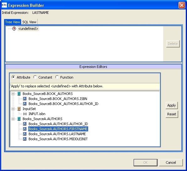
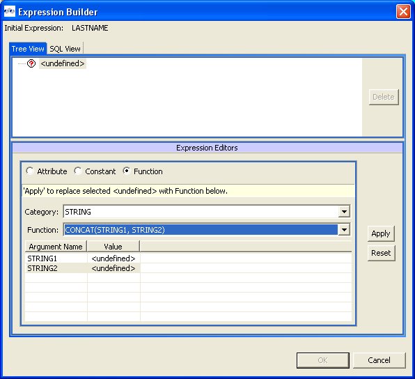
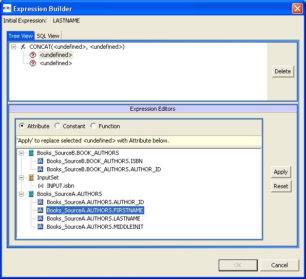
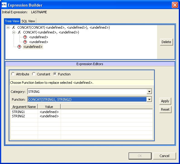
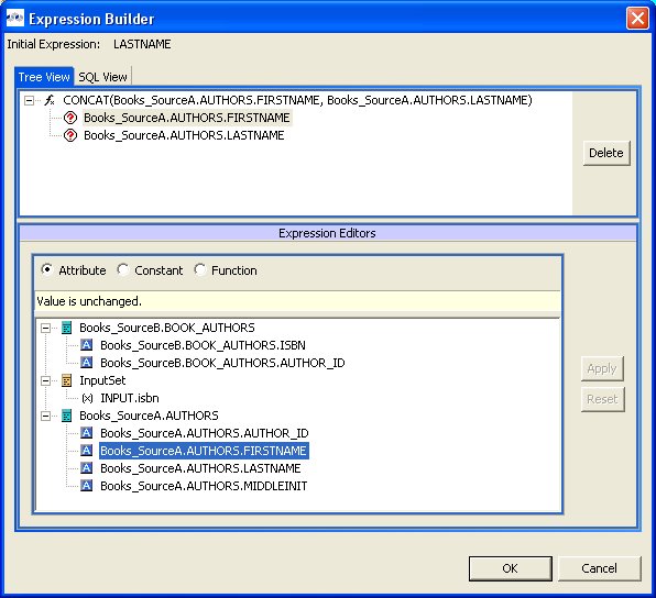
The Input Set represents a special class that contains attributes from a parent mapping class. When you create mapping classes for an XML Document model, the Teiid Designer automatically adds an Input Set to all XML transformation diagrams for mapping classes beneath the highest node in the Document meta object.
The Input Set proves especially useful for information integration using the Teiid Designer Server. Through the Input Set, you can access a row of data generated by any XML transformation in a mapping class higher in the XML document’s hierarchy. You can use Input Set attributes, which are individual columns from the rows of data, within the criteria of an XML transformation query of the child mapping class.
You cannot use the Input Set attributes within the SELECT portion of the XML transformation query.
To use an Input Set, you must use the Input Set Editor to bind attributes from parent classes.
Once you have created an Input Set, you can use the attributes within it as source material for the XML transformation diagram’s query.
The Input Set only serves to enable data flow between nested mapping classes. If you use the Teiid Designer Server for data access, your applications cannot directly query an Input Set. Input Sets only display in the XML transformation diagram to which they belong. Input Sets do not display on the Section 4.1, “Model Explorer View” view and you cannot use them as you would a normal class, such as for source classes in other transformations.
To open the Input Set Editor, either double-click the input set in the Mapping Transformation Diagram or click the edit button on the Input Set in the diagram. (see below)
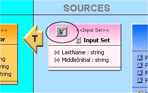
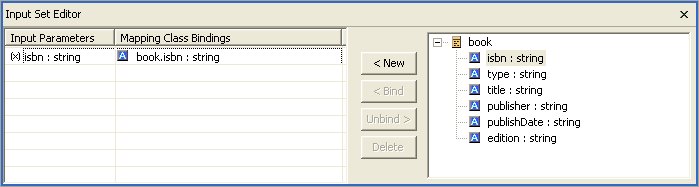
The Input Parameters table contains a list of mapping attributes within the input set and the mapping attributes bound to input set mapping attributes. The tree on the right displays the parent mapping classes and the attributes available from each.
Using the Input Set Editor, you can:
Add a mapping attribute from a parent mapping class to the Input Set. In the tree on the right, select the symbol for which you want to create an attribute and click New. The item displays in the Input Parameters and Mapping Class Bindings table.
Delete a mapping attribute from the Input Set. Click the row in the Input Parameters and Mapping Class Bindings table that you want to delete and click Delete. The Teiid Designer removes this row from the table and this mapping attribute from your Input Set.
Bind and Unbind Input Parameters.
Once you have created the mapping attributes within the Input Set that you need, you can use the Input Set Parameters within a mapping class transformation to produce mapping attributes you can map to your XML document.
Within an XML Document model, a choice compositor defines all possible document data structures (sometimes called fragments) that can appear at that location in an XML instance document. When the Teiid Designer Server populates an XML instance document at runtime based upon your virtual XML document, it will choose the first fragment that matches the criteria you specify within the Choice Editor.
To view the choice editor, right-click on the choice node in the mapping diagram's XML Document tree view and select Edit from the right-click pop up menu.
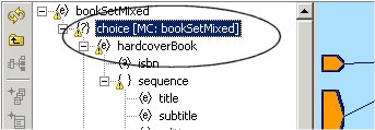
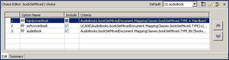
The table on this panel displays fragment options for the choice, each represented by the top node of the document fragment.
The Summary tab, shown below, displays a SQL-like version of the current choice criteria.
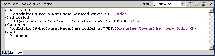
You should address each choice option by performing one of the following:
Specify a criteria statement for the Teiid Designer Server to apply in order to determine which elements or elements to insert into the result document.
Exclude or include the option’s fragment from the document.
Set the elements’ criteria test order.
Set a default action that occurs if none of the criteria you set is met.
The XML Schema upon which you based the XML Document model determines the nature of the options available to the choice. A schema you share with other, external sources (such as business partners) might include information that you do not want to include within XML files.
For example, Sample Financial Services shares an XML schema with its partners Example Mutual Insurance, Illustrative Brokerage, and FinancialPartners.com. The partners created the schema broadly, to cover all possibilities for information they might need to interchange. As such, the customer information XML document might include a choice compositor based on a list of all products all companies offer.
However, Sample Financial does not offer a credit card; so it could exclude those elements from the XML documents its Teiid Designer Server creates since it will never have credit card information for an XML document.
The table on the Choice Editor contains the Include column. By default, all elements specified by the schema are included. You can click to remove the checkmark beside any element you do not want to include within your XML documents generated by this virtual XML document metadata model. By removing the checkmark, you are not removing the element from the XML Document model; you are merely telling the Teiid Designer Server that it will never use this element as part of the choice.
You cannot edit criteria for excluded elements. However, if you exclude an option for which you have established a criteria, Teiid Designer will retain the criteria if you want to include the option in the future.
To edit the criteria for a choice element:
Step 1 - In the table on the Choice Editor panel, select the element you want to edit..
Step 2 - Click Edit Criteria button to launch the Criteria Builder dialog.
Step 3 - Use the Criteria Builder to create the conditions for which the Teiid Designer Server will test to determine whether to choose this option in the XML instance document.
Step 4 - Click OK. The criteria you set displays both in the table and in the summary tab.
You must set a criterion for each option in your document unless you have selected to exclude that option or specify that option will be the default option.
To edit the criteria for a choice element:
The Teiid Designer Server evaluates the choice criteria in the order in which they appear, and when one choice criteria is met, the Teiid Designer Server populates the XML instance document with that option. The Teiid Designer Server might not test all criteria for all options, so their order matters a great deal.
Therefore, the order in which your options appear within the choice criteria often determines what information appears ultimately in your XML instance documents. You can reorder the option list within the choice to set the order in which the Teiid Designer Server tests the criteria.
To set this order, select an element in the table and use the ![]() or
or ![]() button to move it into a new position in the table. The new order
displays both in the table and in the Choice Criteria box and reorders
the XML document as well.
button to move it into a new position in the table. The new order
displays both in the table and in the Choice Criteria box and reorders
the XML document as well.
The default action represents the course the Teiid Designer Server should take if none of the criteria you set evaluates to true.
You can set this default using the combo box available in the Choice Editor's toolbar to:
Any of the options within the table except those you have excluded from the document.
THROW to throw a Teiid Designer Server exception.
RECORD to record the Teiid Designer Server exception.
DISCARD to place no element within the XML instance document.
Note: You must set a default action for your choice criteria.
Some XML schemas define data structures that contain self-referencing elements or datatypes. When generating XML documents, such data structures can produce an endless repetition of nested tags. This self-nesting pattern is known as recursion.
When generating virtual documents from XML Schema, the Teiid Designer detects recursive data structures in the XML Schema model and halts the recursive nesting pattern after two cycles. These two cycles serve different purposes when mapping the document:
The first cycle can be thought of as an “entry condition” for the recursion. The mapping class located at this node defines a normal mapping transformation like that of any other in the document model.
The second cycle defines a mapping transformation that will be performed repeatedly until conditions are met that will halt the document instance being generated by the Teiid Designer Server. This fragment of the document model is called the recursive fragment. The mapping transformation for this fragment is no different from the first, except that you can access the first cycle's mapping class attributes, plus you have the opportunity to specify the conditions that will halt the recursion.
You can recognize a mapping class located at the second, recursive document fragment by the looping arrow button in the top-left-hand corner of the diagram object as shown below.
When you model a virtual document based on an XML Schema model containing recursion, you can choose whether to treat the nested fragments as recursive. You should only use recursion when the data access pattern from your data source(s) is also recursive; in other words, when the same query transformation should be executed over and over to generate and map the nested document's data content.
By default, the Teiid Designer does not mark the recursive fragments in document models to execute recursively in the Teiid Designer Server. To take advantage of this behavior, you must open the Recursion Editor in the recursive mapping class mapping transformation diagram, mark the transformation query as recursive, and specify the recursion limit properties.
The Recursion Editor lets you enable and limit recursion. The Recursion Editor button only displays on mapping classes, which have recursive patterns. For example, if you have an element named Employee which contains a element named Supervisor which itself contains an Employee element nested within it, you might need to limit the number of times the elements are nested within the document.
You can set the following conditions to limit the recursion:
A fixed number of results to the query.
A SQL-based criteria limit condition.
A combination of both.
To open the Recursion Editor, click on the Recursion Editor
button ![]() on the displayed mapping class.
on the displayed mapping class.
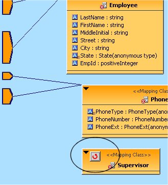
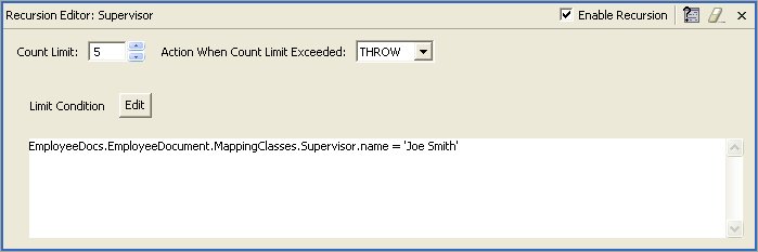
To edit recursion properties:
Step 1 - Click the Enable Recursion check box if you want the Teiid Designer Server to perform the query you specify to generate the nested tags within the XML document.
Step 2 - Click the arrows beside the Count Limit box to limit the number of times to recursively perform the query. If you do not set a Limit Condition in the text area, the recursion finishes when the query reaches this limit. You can only set this limit to a maximum supported by your Teiid Designer Server. For more information about this limit, contact your system administrator
Step 3 - Click the Action When Count Limit Exceeded drop down menu to instruct the Teiid Designer Server what to do if it encounters more results for the query than the count limit before it reaches the limit condition.
Step 4 - Click the Edit button to launch the SQL Criteria Builder to build a limiting condition for this recursion.
Note
The Teiid Designer Server will evaluate this condition each time it recursively performs this query. If this criteria clause evaluates false, the Teiid Designer Server performs the query recursively again unless it has reached the Count Limit. If the criteria evaluates true, the Teiid Designer Server performs the mapping for the current level and ends its recursive loop.
When you have created the criteria, it displays in the Limit Condition box.
When the Teiid Designer Server dynamically populates your XML documents at runtime, it will use the recursion specifications you entered here.
Editing of Web Service Operation transformations is simplified via the Operation Editor. When editing a Web Service model, an additional editor tab labeled "Operation Editor" is available. This editor, shown below is comprised of:
Operations section showing a tree view of Interfaces and Operations contained within the Web Service model.
Input Variables section providing editing of desired Input Variable declarations.
Procedure section providing SQL editing of the procedure (See Mapping Web Service Operations).
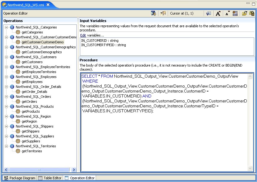
The Operations section contains all interfaces and operations currently defined in the model.
Selecting an operation will display the variables related to the input parameter's content in the Input Variables section and the body of its procedure (minus the CREATE VIRTUAL PROCEDURE BEGIN - END keywords and the input variable declarations and assignments) in the Procedure section.
When pasting in SQL, do not include the CREATE VIRTUAL PROCEDURE BEGIN - END keywords. Input variables will be automatically generated when the "Content via Element" property is set on an operation's input parameter. Input variables may be created, edited, or deleted using the Edit link in the Input Variables section, and may only represent XPath values to single attributes and elements within the input contents; other variable declarations and assignments must be typed directly into the Procedure section. Clicking the Edit link will display the following dialog:
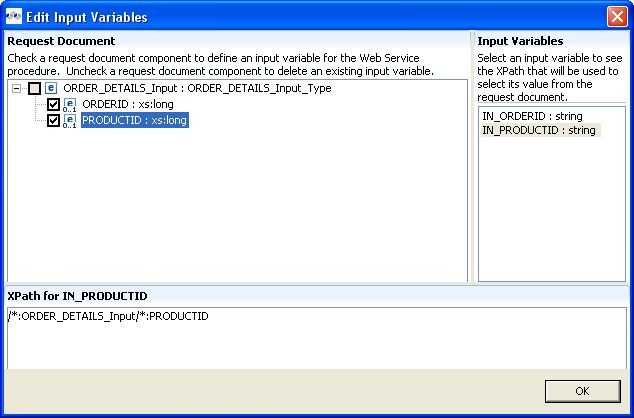
Input Variables can be deleted via right-click menu Delete action (see figure below) for selected variables or using Cntl-X, Delete keys. You can also rename an Input Variable using the right-click menu Rename action or the F2 key. ( Note: Input variables names have to be named starting with the "IN_" characters. Renaming a variable will always insure its name is prepended with "IN_").
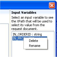
Go To: Table of Contents
Teiid Designer offers three basic model edit actions: Rename, Move and Save As... and one project-related action, Clone Project. These actions are described below.
To rename a model in your workspace:
Step 1 - Select a model in the Section 4.1, “Model Explorer View”.
Step 2 - Right-click select the Refactor > Rename action.
Step 3 - Specify unique model name in the Rename Model File dialog. Click OK.
Note
Renaming a model that is a dependency to another model will automatically change the model imports for those models. If source model CustomerSource is renamed to OldCustomerSource, for instance, the import statement for the view model CustomerAccounts which imports CustomerSource will be changed to reflect the new name.
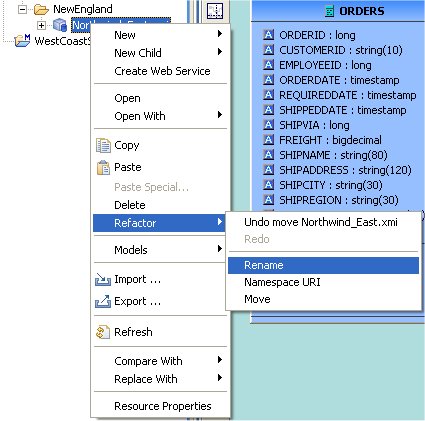
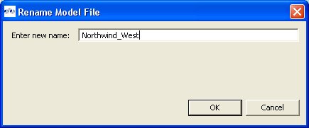
To move a model in your workspace:
Step 1 - Select a model in the Section 4.1, “Model Explorer View”.
Step 2 - Right-click select the Refactor > Move action.
Step 3 - Select a new location (i.e. Project or Folder) and click OK.


The Save As... action performs a similar function as the Refactor Rename action except the renamed model a structural copy of the original model.
Note
Each model object maintains it's own unique ID, so copying a model will result in a exact structural copy of your original model but with re-generated unique object IDs. Be aware that locating and copying your models via your local file system may result in runtime errors within Designer. Each model is expected to be unique and duplicate models are not permitted.
To create a duplicate model using Save As...:
Step 1 - Open the model you wish to copy in a Model Editor by double-clicking the model in Section 4.1, “Model Explorer View” or right-click select Open action.
Step 2 - Select the editor tab for the model you opened.
Step 3 - Select File > Save As... action to open the Save Model As dialog.
Step 4 - Enter a unique model name in the new model name text field and click OK.
Step 5 - If dependent models are detected, the Save Model As - Import References dialog is presented to give you the opportunity to change any of the dependent models imports to reference the new model or not.
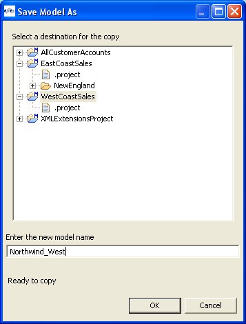
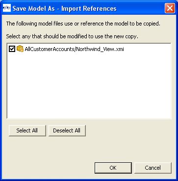
Because each instance of of a model contains a unique ID and each object in each model contains a unique ID, copying a project is a delicate task. For this reason, the Clone Project action was created to manage the creation of exact structural copies of all models in the source project.
The following lists specific rules and limitations for this action.
This action clones a complete model project containing any number of model (XMI or XSD) files organized in a user-defined directory structure.
All object references (UUIDs) within the original project will be replaced with new unique references.
Any model dependencies or internal object references are refactored to reflect the dependencies within the cloned project.
Any model references to models in projects external to the original project will NOT be replaced.
Only XMI and XSD files are cloned. All other file types in your project will NOT be processed nor copied into your newly cloned project including VDBs
If one or more editors that require "save" are open, the user will be asked to save them before continuing with the cloning process.
To clone a model project::
Step 1 - Select an existing model project in the Section 4.1, “Model Explorer View”.
Step 2 - Right-click select the Clone Project action or select the Project > Clone Project action located in the Teiid Designer’s main menu bar.
Step 3 - On the Clone Project wizard page, provide a name for your new project.
Step 4 - (Optional) If you wish to create your cloned project in a location other than your default workspace location, uncheck the Use default check-box and specify (type in or browse to) a new directory location on your local file system.
Step 5 - Click Finish to generate your new project.
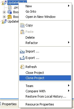
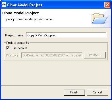
Go To: Table of Contents
As described briefly in Chapter 1, you can test your models in Teiid Designer by using the
Preview Data action ![]() . You can also test your models via your deployable VDB. These two options will be described in detail in this chapter
as well as managing your required connectors.
. You can also test your models via your deployable VDB. These two options will be described in detail in this chapter
as well as managing your required connectors.
In order to test your data, the Teiid Designer requires applicable connector information. This information is stored in the properties of a Connector. The Teiid Designer provides a Connectors view for managing your connectors and this section summarizes its features and capabilities.
To edit properties of a connector, you can either select the connector and edit the properties in the Properties view, or select the Edit action and open the Connector Editor dialog presented below. Select the applicable 'Value' to activate the individual value editor.
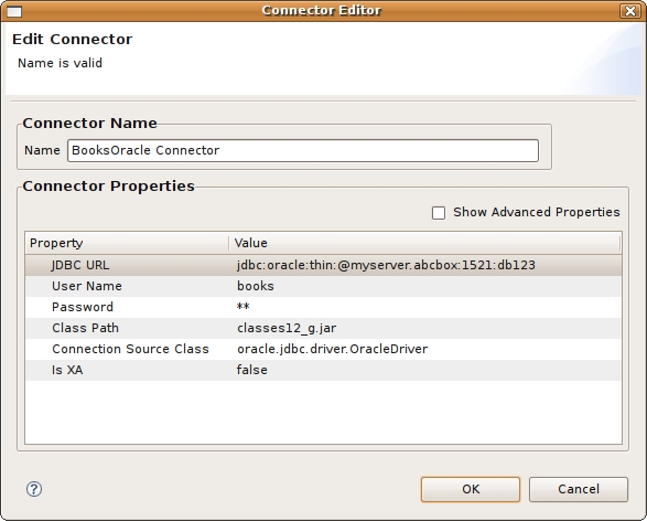
Create a new connector by either selecting the New Connector action in the Connectors view toolbar or right-click select the same action from the context menu. If connector types are displayed in the Connectors view, you can select a connector type first, then select the New Connector action. This will pre-select the type in the New Connector dialog. The action will launch the New Connector dialog shown below. Provide a valid connector name, select desired connector type, enter your custom properties and click OK to create you new connector.
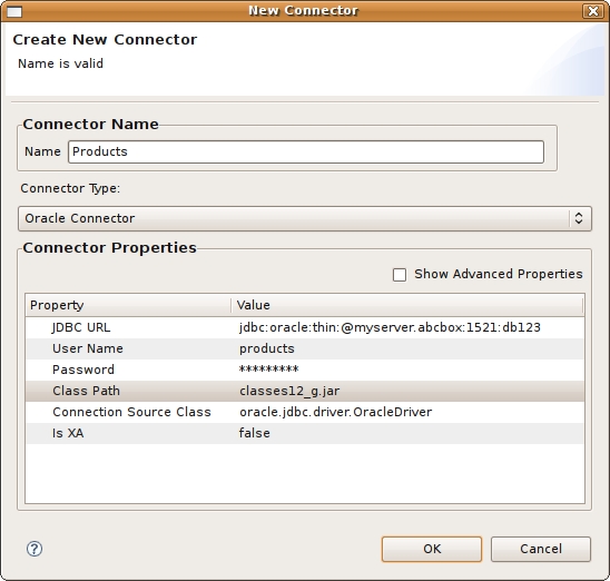
In order to preview your data, you'll need to bind your source models to valid connectors. If you import your source from JDBC, your connector will be created during the import process and your source automatically bound to that connector.
You can bind, unbind or change source bindings in a couple of ways.
To bind a source, you can:
Select a model in the Section 4.1, “Model Explorer View” view select the Modeling > Connector >> Bind action. This action presents a dialog for selecting your desired existing Connector. Select a binding and click OK.
Select a model in the Section 4.1, “Model Explorer View” view and drag the model into the Connectors view and drop into the desired existing Connector.
To unbind a source:
Select the source model in Connectors view and right-click select the Unbind action.
Select the model in the Section 4.1, “Model Explorer View” view and select the Modeling > Connector >> Unbind action.
You can import your custom connector types and connectors into Designer. These connectors can be in the form of a *.cdk file (i.e. exported from Designer) or from a *.caf (connector archive file) defined during connector development.
To import connector types and/or connectors:
Step 1 - Select the Import Connectors (*.cdk, *.caf) action
located in the Connectors view
toolbar or in the right-click menu.Step 2 - In the first wizard page, Select the Import... button to select your *.cdk or *.caf file on your local file system. This page presents a summary of the custom connector types defined in your cdk/caf file. Use the check-boxes in the table to choose which types to import. Select Next> to view additional connector and jar import options or click Finish (if enabled) to import selected types and all associated connectors and connectors jars. Note: This wizard page contains a details panel which displays status messages for selected connector types.
Step 3 - The second wizard page contains connector types defined in your cdk/caf file. Use the check-boxes in the table to choose which bindings to import. Select Next> to view additional jar import options or click Finish (if enabled) to import selected types, bindings and all associated connectors jars. Note: Note: This wizard page contains a details panel which displays status messages for selected connector types.
Step 4 - The last wizard page contains connector jars defined either in your caf file or jars located in the same file system folder as the initial cdk file. If while importing a cdk file the required jars are not present in the selected file system folder, select the Find... button to locate and select the required jar from your local file system.
Notes
1) This wizard page contains a details panel which displays status messages for selected connector types.
2) The Finish button will not enable until all custom connector jars are identified and defined. These jar files are defined in the classPath property for both connectors and connector types.
Step 5 - Click Finish to complete the import.
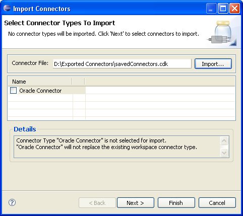
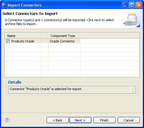
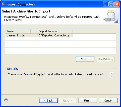
You can export your custom connectors from Teiid Designer into a *.cdk file.
To export connectors:
Step 1 - Select one or more Connectors in the Connectors view.
Step 2 - Select the Export Connectors (*.cdk) action
located in the Connectors view
toolbar or in the right-click menu.Step 3 - In the wizard, select a location on your local file system and specify a *.cdk file name (default is: savedBindings.cdk)
Step 4 - Click Finish to complete the import.
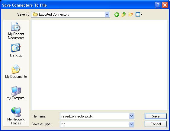
After creating your models, you can test them by using the
Preview Data action ![]() . By selecting a desired table object and
executing the action, the results of a simple query will be displayed
in the Preview results view. This
action is accessible throughout the
Teiid Designer in various view toolbars and context menus.
. By selecting a desired table object and
executing the action, the results of a simple query will be displayed
in the Preview results view. This
action is accessible throughout the
Teiid Designer in various view toolbars and context menus.
There are two requirements for previewing your data: the selected object must be one of several previewable model object types and all source models within the model dependency tree must be bound to connectors. Model objects that can be previewed include: relational tables and views (including tables involving access patterns), relational procedures, Web service operations and XML document staging tables.
Note that any virtual table, view or procedure is previewable as long as all "physical" source models are bound via connectors. (See Connectors view )
Testing Your Transformations
When editing transformation SQL in the Transformation Editor, a special Preview data action is provided in the
editor tool-bar ![]() .
.
You can change your transformation SQL, re-validate and preview your the data for your modified SQL.
The following sections provide steps for previewing your data. Note that all steps assume that all source models referenced by your models, either directly or through dependencies, are bound to connector bindings.
To preview a relational table, relational view or staging table:
Step 1 - Select a relational table or view in the Section 4.1, “Model Explorer View” or diagram. The table or view can be in a view model as well as a source model. Staging tables are not visible in the Section 4.1, “Model Explorer View”, so you need to open the mapping diagram and select it there.
Step 2 - Right-click select the Preview Data action
. You can also select the same action in the tool-bar of either
the Section 4.1, “Model Explorer View” or diagram. Step 3 - Your query results will be displayed in the Preview results view. The view will automatically open or get focus if not visible in your perspective.
To preview a relational table or view with access pattern:
Step 1 - Select a relational table or view in the Section 4.1, “Model Explorer View” or diagram that contains an access pattern. The table or view can be in a view model as well as a source model.
Step 2 - Right-click select the Preview Data action
. You can also select the same action in the tool-bar of either
the Section 4.1, “Model Explorer View” or diagram. Step 3 - A column input dialog is presented. Select each access pattern and enter a value for each required column. Note that if data entered does not match the column datatype (String, integer, etc...), an error message will be displayed in the dialog header. When all required values are entered, click the OK button to execute the query.
Step 4 - Your query results will be displayed in the Preview results view. The view will automatically open or get focus if not visible in your perspective.
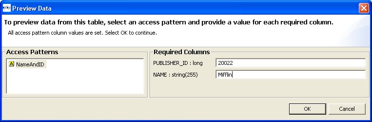
To preview a relational procedure:
Step 1 - Select a relational procedure in the Section 4.1, “Model Explorer View” or diagram. The procedure can be in a view model as well as a source model.
Step 2 - Right-click select the Preview Data action
. You can also select the same action in the tool-bar of either
the Section 4.1, “Model Explorer View” or diagram. Step 3 - An input parameter input dialog is presented. Enter a valid value for each parameter. Note that if data entered does not match the parameter datatype (String, integer, etc...), an error message will be displayed in the dialog header. When all required values are entered, click the OK button to execute the query.
Step 4 - Your query results will be displayed in the Preview results view. The view will automatically open or get focus if not visible in your perspective.
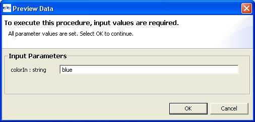
To preview a Web service operation:
Step 1 - Select a Web service operation in the Section 4.1, “Model Explorer View” or diagram. The operation can be in a view model as well as a source model.
Step 2 - Right-click select the Preview Data action
. You can also select the same action in the tool-bar of either
the Section 4.1, “Model Explorer View” or diagram. Step 3 - An input parameter input dialog is presented. Enter a valid value for each parameter. Note that if data entered does not match the parameter datatype (String, integer, etc...), an error message will be displayed in the dialog header. When all required values are entered, click the OK button to execute the query.
Step 4 - Your query results will be displayed in the Preview results view. The view will automatically open or get focus if not visible in your perspective.
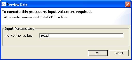
To execute a query against your VDB:
Step 1 - In the Section 4.1, “Model Explorer View”, double-click a VDB, or select one and choose Open action to open a VDB Editor.
Step 2 - Select the Execute tab. If connectors are missing for any source models, the Execute button will be disabled. Edit your connectors to create/select connectors for your models.
Step 3 - Select the Execute button to establish a connection and open the SQL Explorer perspective. Your VDB should now be connected via the connectors defined previously. Verify the connection in the Connections view.
Step 4 - In the Database Structure view (upper left), expand the Table node to list the tables in your VDB.
Step 5 - Select one of the tables and do a right click. Select the Generate Select in SQL Editor menu item.
Step 6 - A SELECT statement will appear in the SQL Editor (upper right).
Step 7 - Click the Execute SQL icon
to run the query. The results will appear in the SQL Results tab (lower right).
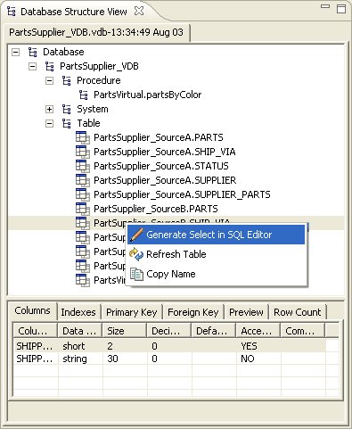
When executing queries on XML View Documents, the results are displayed in XML format as shown below:
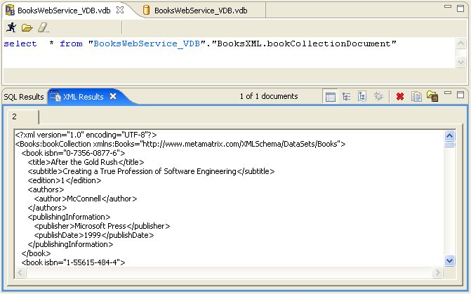
When each query is executed, the SQL is stored in the SQL History table so the queries can be re-submitted without re-typing it.
This content of this SQL History table can be edited via right-click menu shown below.
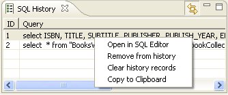
Saving Your Query Results
Query results, both SQL and XML, can be saved to text files in the SQL Explorer perspective.
The toolbars for SQL Results and XML Results views contains an additional action/button (see below) which presents a file save dialog. Note that the action can also be accessed via the right-click menu on both views.

In addition, this file save dialog is presented to the user when the XML Document results exceed the character size limit defined by a user preference property for the SQL Explorer.
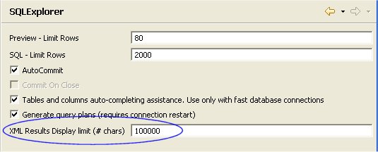
When this limit is exceeded, the user is presented with a dialog to either save the results to a file or continue displaying the results and possibly incurring substantial runtime memory allocation.
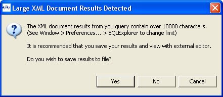
When the Save option is accepted, the XML Query Results view displays the file name and path of the exported file.
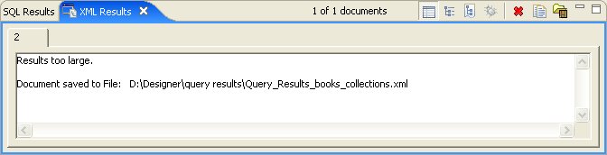
Go To: Table of Contents
The Teiid Designer provides multiple search actions located in the main toolbar's Search menu.
The individual actions in the Search menu are described below:
- Search... - Launches the
standard Search dialog, which can be used to find resource containing specific
text or expressions and filter based on file name patterns. For standard Eclipse
installations, the default search tile will be File Search. (See Eclipse documentation for details).
- File... - Launches the
standard Search dialog, which can be used to find resource containing specific
text or expressions and filter based on file name patterns. The File Search
tab will be selected in the dialog. (See Eclipse documentation for details).
- Find Model Object - Launches the
Find Model Object dialog, which can be used to locate an
object in the workspace by specifying all or part of its name. Selecting the object
will open it in the appropriate editor.
- Relationship... - Launches the
Search dialog and auto-selects the Relationships tab. Users can search for models in the workspace
by specifying a relationship type, participant locations, and/or names containing specified
text. Search results appear in
the Search Results view,
and double-clicking a result will open that model in the appropriate editor.
- Transformations... - Launches the
Transformation Search dialog. User can search models in
the workspace for matching SQL text. Search results appear in the
dialog and user can select and view SQL as well as open desired transformations for editing.
- Metadata... - Launches the
Search dialog. User can search for models in the workspace by
specifying an Object Type, and/or a Data Type, and/or a property value.
Search results appear in
the Search Results view,
and double-clicking a result will open that model in the appropriate editor.
The Teiid Designer provides a name-based search capability to quickly locate and display model objects.
To find a model object:
Step 1 - Open the Find Model Object dialog by either selecting the
action on the main Teiid Designer tool-bar.or select the same action via the main menu's Search > Find Model Object
action. Step 2 - Begin typing a word or partial word in the Type Object Name field. Wild-card (*) characters will be honored. As you type, the objects which match the desired name will be displayed in the Matching Model Objects list. If there are more than one objects with the same name, the locations or paths of the objects are displayed in the Locations list.
Step 3 - If more than one object exists with the desired name, select the one of the locations.
Step 4 - Click OK. If editor is not open for the object's model, an editor will open. The desired object should end up displayed in a diagram (if applicable) and selected.
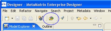
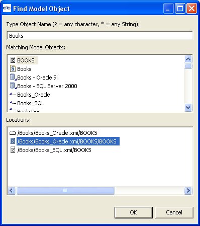
The Teiid Designer provides a search capability to find model objects that are characterized by one or more relationship property values including relationship type, participants and name.
To search for relationships:
Step 1 - Select Search > Relationships... action on the Teiid Designer main menu
which opens the Search dialog.Step 2 - Specify desired search options for Object Type, location of Participants and Name.
Step 3 - Click Search. The search will be performed and the results will be displayed in the Search Results View. If the view is not yet open, it will be opened automatically.
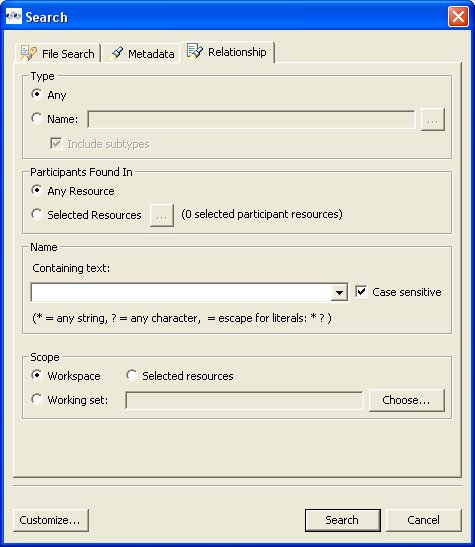
The Teiid Designer provides a search capability to string values present in transformation SQL text.
To search for string values in your transformations SQL:
Step 1 - Select Search > Transformations... action on the Teiid Designer main menu
which opens the Search Transformations dialog.Step 2 - Specify a string segment in the Find: field and specify/change your case sensitive preference.
Step 3 - Select Perform Search button. Any transformation object containing SQL text which contains occurances of your string will be displayed in the results section.
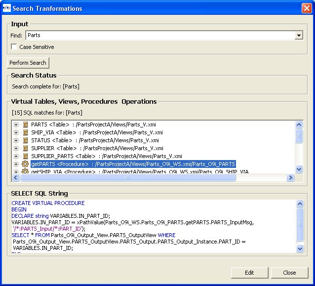
You can select individual objects and view the SQL. If a table or view supports updates and there is insert, update or delete SQL present, you can expand the object and select the individual SQL type as shown below.
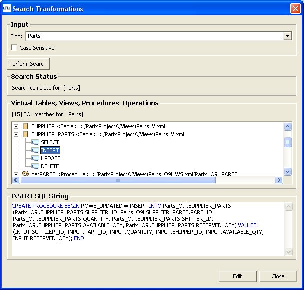
If you wish to view the selected object and its SQL in a Model Editor, you can click the Edit button. An editor will be opened if not already open. If an editor is open its tab will be selected. In addition, the Transformation Editor will be opened and you can perform Find/Replace (Ctrl-F) actions to highlight your original searched text string and edit your SQL if you wish.
The Teiid Designer provides a search capability to find model objects that are characterized by one or more metadata property values.
To search your models using metadata:
Step 1 - Select Search > Metadata... action on the main Teiid Designer toolbar
which opens the Search dialog.Step 2 - Specify desired search options for Object Type, Data Type and Properties.
Step 3 - Click Search. The search will be performed and the results will be displayed in the Search Results View. If the view is not yet open, it will be opened automatically.
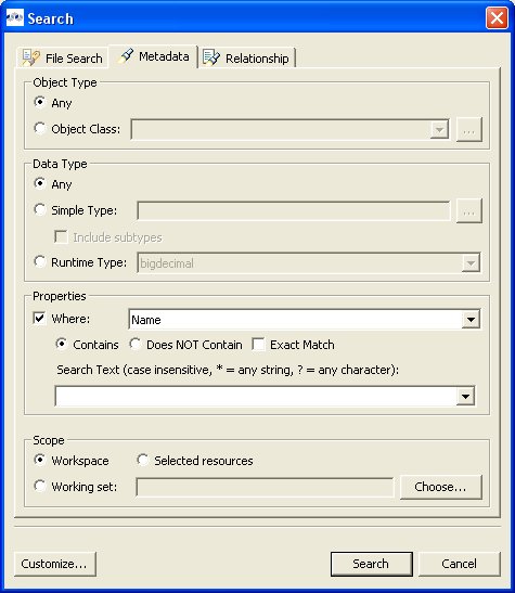
Go To: Table of Contents
Introduction
The Teiid Designer includes the ability to create named relationships between almost any two or more modeling elements.
The Relationship metamodel is one way to define arbitrary associations between two or more metadata entities. Using the Relationship metamodel, the Teiid Designer provides users the ability to view, add, and edit associations between metadata entities.
But the Generic Relationships functionality can define relationships between metadata entities from different metamodels. For example, it is possible to create a generalized relationship between a Relational Column and a UML Package.
Users can even define their own relationship types that constrain the numbers and types (metaclasses) of objects that can be related.
Once the existing relationships are defined, the Teiid Designer provides a number of mechanisms that will make use of those relationships. This includes navigating to a related object, searching for relationships based on some criteria, or diagramming the relationship of various sets of objects
To create a relationship in a diagram:
Step 1 - First select the source element of the relationship.
Step 2 - Then Shift+Click on the second target element. Right-click and select New Association > Relationship.
Step 3 - In the Create Relationship dialog, supply a valid name for your relationship, Browse... and select a relationship type.
Step 4 - Click the Browse... button adjacent to the Type field and open the Select Relationship Type dialog and select an existing relationship type that best describes your relationship.
Step 5 - Click the Browse... button adjacent to the Location field and open the Relationship Model Selector Dialog. If a relationship model already exists, you can select it and click OK. If not, select a valid project or folder and provide a valid name for a new relationship model which will be created for you, then click OK.
Step 6 - If you wish to add additional objects to either your source or target participants, click the Add... button to display the Model Object Finder dialog. You can either browse your workspace (Workspace tab) and select objects within models, or click on the Finder tab and type in known object names to search for specific objects by name. Click OK to add selected objects to the participant lists.
Step 7 - You can also edit your relationship properties by selecting the Properties tab in the Create Relationship dialog.
Step 8 - Click Finish to complete the relationship. The new relationship will be displayed in a relationship diagram.
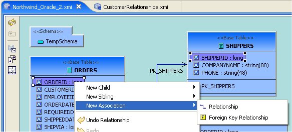
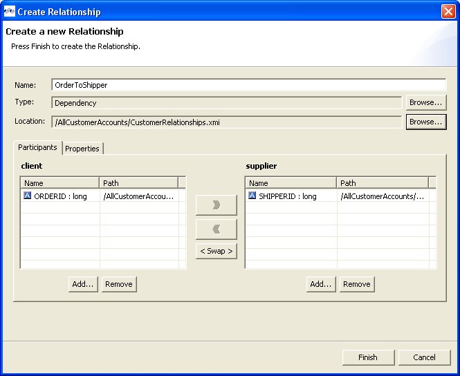
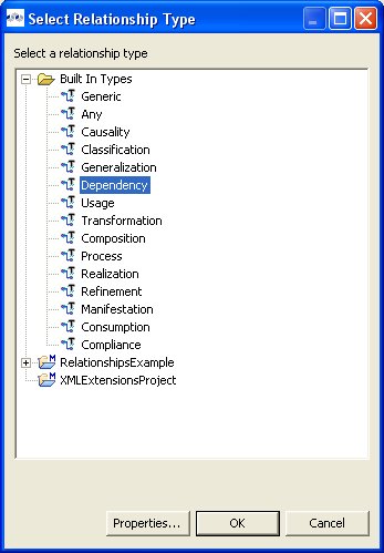
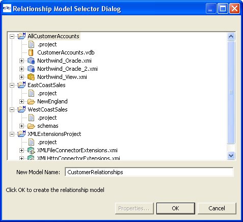
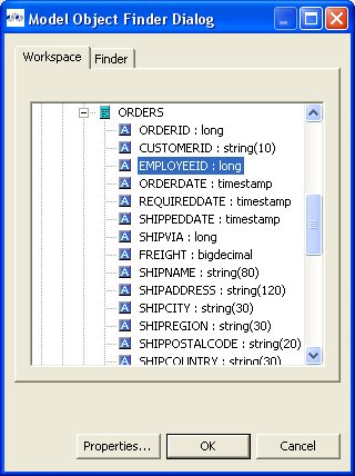
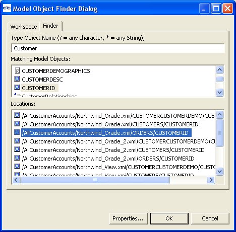
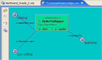
To create a relationship from the Section 4.1, “Model Explorer View” tree, select two or more objects in the tree, right-click select New Association > Relationship action and follow Steps 3 thru 8 described above.
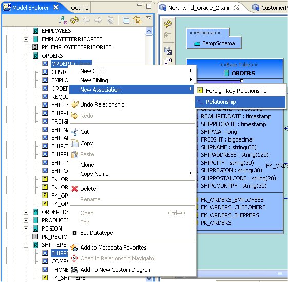
To create a new relationship type:
Step 1 - Select an existing Relationship model in the Section 4.1, “Model Explorer View” or a folder within the model. If a Relationship model does not yet exist, create one. See New Model Wizard.
Step 2 - Right-click select the New Child > Relationship Type action.
Step 3 - In the Create Relationship Type dialog, supply a name for your new relationship type.
Step 4 - Select on Role A and Role B tabs in the dialog and specify role names, Add... any Metaclasses you wish to specifically Include as possible participants. You can also specifically Exclude metaclasses.
You can also change role properties via the Role Properties... button which launches a properties editor dialog.
Step 5 - Select the Inheritance tab.
Step 6 - Launch the Select Relationship Type dialog via the Browse... button. Choose a base relationship type that best describes your category of relationship. Click OK.
Step 7 - Select the Properties tab and change/set relationship type property values.
Step 8 - Click Finish to create relationship type.
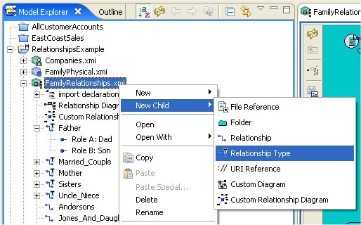
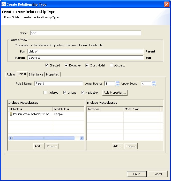
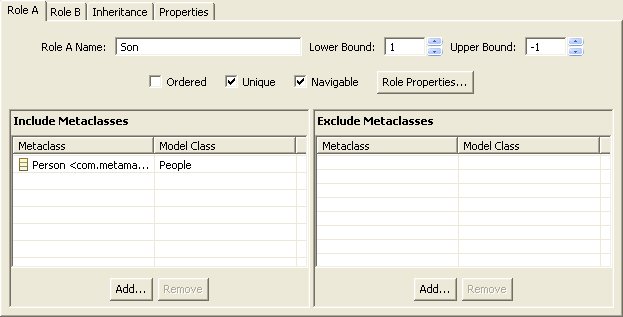
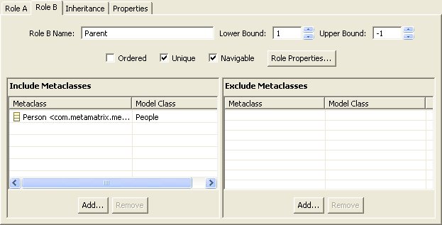
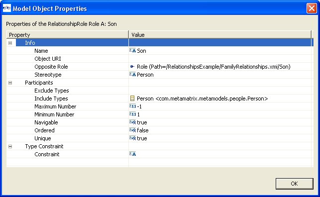

A Relationship Navigator view provides a unique way of viewing and navigating your relationships. It can be very useful in understanding associations between complex and visibly unrelated data.
To open the Relationship Navigator you can select the Window > Show View > Relationship Navigator action (if available) or open the Show View dialog via Window > Show View > Other... and open the Teiid Designer folder and select Relationship Navigator .
You can also quick-launch the navigator by selecting any object in the Section 4.1, “Model Explorer View” or a Model Editor and right-click select the Open in Relationship Navigator action.
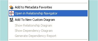
In the example presented here, the diagram below illustrates the standard role-based relationships defined for a family.
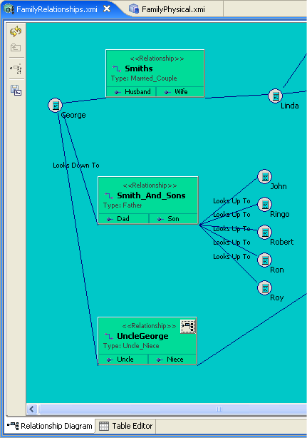
This action opens the Relationship Navigator in the same panel as the Properties and Description views.
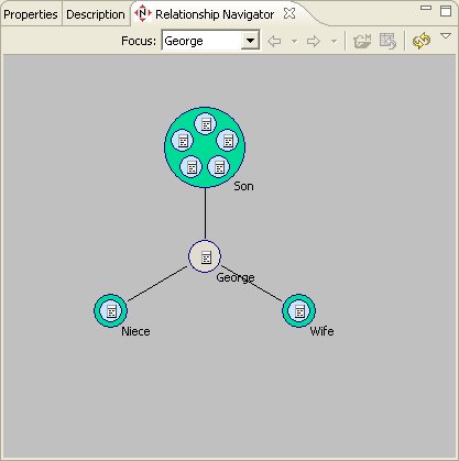
The visible detail in the navigator is limited in order to simply navigation. You can, however, show detailed information about the navigation/relationship nodes by hovering your mouse and showing tooltips.
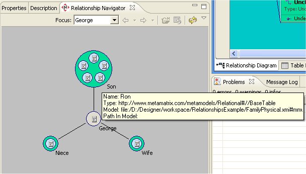
At the center of the navigator is the focused node, which represents the base or frame of reference for the displayed navigation. In this sample above, George has a wife, a niece and 5 sons. The relationship diagram shown below illustrates the role based view of these same relationships.
You can navigate to through your relationships by double-clicking an end-node in one of the relationships. For instance, double-click the Son Ron in the upper end-node and the navigator now focuses on Ron and his relationships. You can also right-click and select the Follow Relationships action.
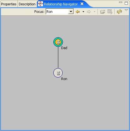
As you navigate, a blue ball will animate the direction of the relationship flow first too the focused object then into the end of the relationship containing the initial focused object.
The navigator also provides toolbar and right-click menu actions to perform various functions in the navigator.
Go To: Table of Contents
The Teiid Designer provides options or preferences which enable customization of various modeling and UI behaviors. Preferences can be accessed via the Edit > Preferences action on the Main toolbar.
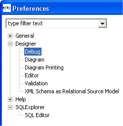
General Teiid Designer preferences include.
Always open editor without prompting To change/edit a model, it must be opened for editing. Checking this box will automatically open the model in an editor if the user attempts to perform a change in a model. If unchecked, the user will be informed that an editor will be opened before the operation is completed.
Check and update imports during save occasionally editing a model may add or remove objects in one model that reference objects in another model. Model Imports keep track of these dependencies within each model. A validation error or warning may appear during a build. Checking this box will automatically check and update imports during the save process. This will result in any unneeded imports being removed from the model or any required imports added to the model. If unchecked, no updating of imports will be performed.
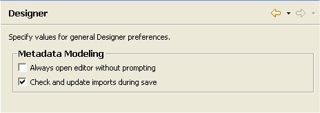
Several diagram preferences are available to customize your diagrams.
Notations - Standard diagram notation for Teiid Designer is based on UML notation. Future releases may include alternate notations.
Routers - The relationship link type for Package and Custom diagrams (Foreign Key - Primary Key relationships) can be customized. Available options include Orthogonal (default), Direct or Manual (user defined breakpoints).
Font Settings - Select font type, style and size.
Background Color Settings - Select a unique background color for each diagram type to help differentiate between types.
Model Size - Displaying very large diagram may take a considerably long time. This preference allows users to set an upper limit on the number of objects to display in a diagram. If this limit is exceeded, a warning is displayed to the user and the diagram is not constructed.
Relationship Options - UML-type relationships can be customized in a couple of ways. Role Names and Multiplicity labels can be shown or hidden using the check-boxes labeled Show Role Names and Show Multiplicity.
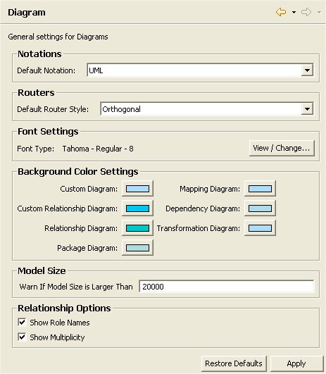
Diagram print options are stored as preferences. These can be accessed through
this preference page, by right-click on diagram Page Setup action ![]() ,
or via the Modify Diagram Printing Preferences action
,
or via the Modify Diagram Printing Preferences action ![]() located on the vertical diagram toolbar .
located on the vertical diagram toolbar .
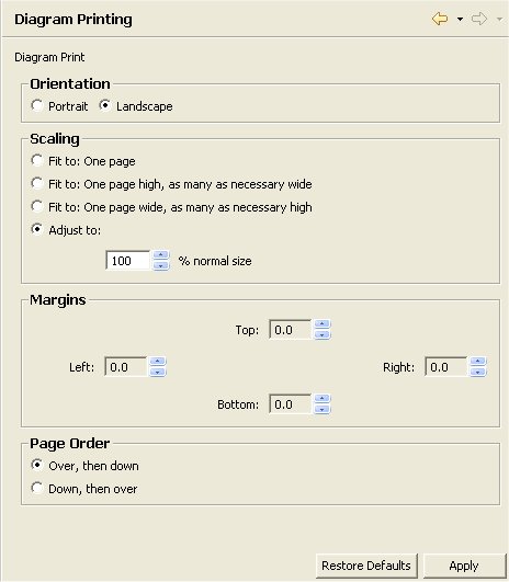
XML Document Mapping Preferences provide ways to customize XML Mapping Diagram and Recursion Editor behavior.
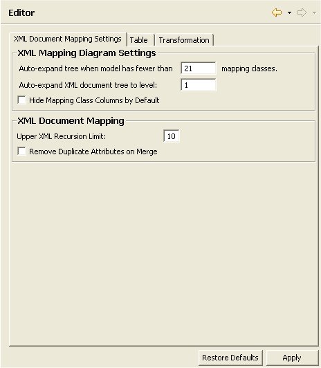
Table Editor Preferences provide a way to customize the order and the information content for each model object type.
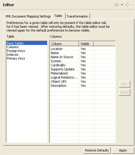
Transformation Editor Preferences provide a way to customize SQL formatting, diagram layout, and default view entity properties.
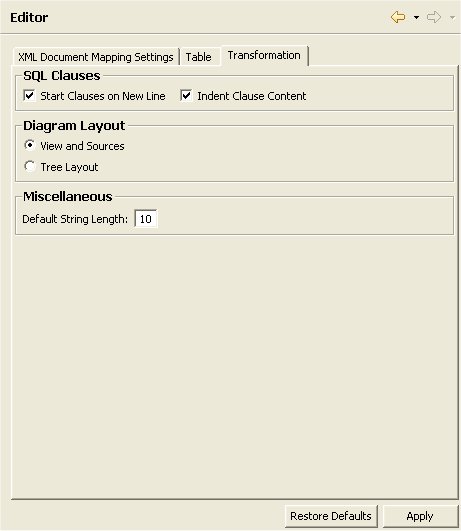
Validation Preferences provide a way to customize the severity of some of the rules checked during model validation.
Validation preference pages, shown below, include Core, Data Access, Relational Model, XML-related and XML Schema (XSD) models.
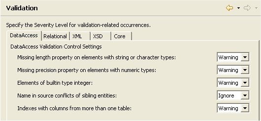
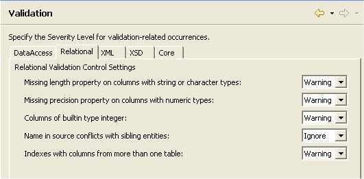
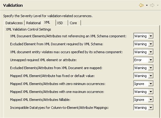
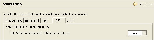
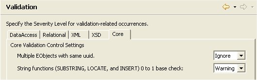
Note
Increasing the severity level to error will prevent you from testing your VDB or deploying a web service if violations of that preference are found during validation.
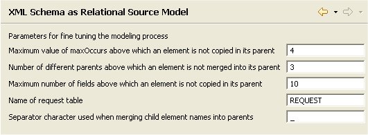
SQL Explorer Preferences provide a way to customize the result preview row count and the actual result row count. If a query plan should be generated each time a query is executed, keep the Generate query plans preference checked. Note: Changes to this preference do not affect existing connections.
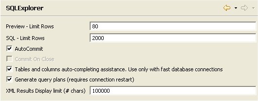
SQL Editor Preferences provide a way to customize the font properties of the editor and the separator character used when exporting results to the clipboard.