The PVM library doesn't have a fixed set of process constructs. Instead, runtime behaviour of a node is delegated to an Activity. In other words, Activity is an interface to implement the runtime behaviour of process constructs in plain Java. Also, Activity implementations can be subscrribed as listeners to process events.
public interface Activity extends Serializable {
  void execute(Execution execution) throws Exception;
}
Activity's can be used as node behaviour and as listeners to process events. When an activity is used as the node behaviour, it is in full control of the further propagation of the execution. In other words, a node behaviour can decide what the execution should do next. For example, it can take a transition with execution.take(Transition), go into a wait state with execution.waitForSignal(). Or the node behaviour can not invoke any of the above, in that case the Process Virtual Machine will just proceed the execution in a default way.
Events are only fired during process execution. Since during an event the execution is already 'in motion', event listeners can not control the propagation of execution. Therefore, Activity implementations can only be used as event listeners if they don't invoke any of the execution propagation methods.
This way, it is very easy to implement automatic activities that can be used as node behaviour as well as event listeners. Examples of automatic activities are sending an email, doing a database update, generating a pdf, calculating an average, etc. All of these can be executed by the process system and they can be used both as node behaviour as well as event listeners. In case they are used as node behaviour they can rely on the default proceed behaviour.
We'll start with a very original hello world example. A Display activity will print a message to the console:
public class Display implements Activity {

  String message;

  public Display(String message) {
    this.message = message;
  }

  public void execute(Execution execution) {
    System.out.println(message);
  }
}
Let' build our first process definition with this activity:

ProcessDefinition processDefinition = ProcessFactory.build()
    .node("a").initial().behaviour(new Display("hello"))
      .transition().to("b")
    .node("b").behaviour(new Display("world"))
.done();
Now we can execute this process as follows:
Execution execution = processDefinition.startExecution();
The invocation of startExecution will print hello world to the console:
hello
world
One thing already worth noticing is that activities can be configured with properties. In the Display example, you can see that the message property is configured differently in the two usages. With configuration properties it becomes possible to write reusable activities. They can then be configured differently each time they are used in a process. That is an essential part of how process languages can be build on top of the Process Virtual Machine.
External activities are activities for which the responsibility for proceeding the execution is transferred externally, meaning outside the process system. This means that for the system that is executing the process, it's a wait state. The execution will wait until an external trigger is given.
For dealing with external triggers, ExternalActivity adds two methods to the Activity:
public interface ExternalActivity extends Activity {

  void signal(Execution execution,
              String signal,
              Map<String, Object> parameters) throws Exception;

  Set<SignalDefinition> getSignals(Execution execution) throws Exception;

}
Just like with plain activities, when an execution arrives in a node, the execute-method of the node behaviour is invoked. In external activities, the execute method typically does something to transfer the responsibility to another system and then enters a wait state by invoking execution.waitForSignal(). For example in the execute method, responsibility could be transferred to a person by creating a task entry in a task management system and then wait until the person completes the task.
In case a node behaves as a wait state, then the execution will wait in that node until the execution's signal method is invoked. The execution will delegate that signal to the behaviour Activity of the current node.
So the Activity's signal-method is invoked when the execution receives an external trigger during the wait state. With the signal method, responsibility is transferred back to the process execution. For example, when a person completes a task, the task management system calls the signal method on the execution.
A signal can optionally have a signal name and a map of parameters. Most common way on how node behaviours interprete the signal and parameters is that the signal relates to the outgoing transition that needs to be taken and that the parameters are set as variables on the execution. But those are just examples, it is up to the activity to use the signal and the parameters as it pleases.
The getSignals-method is optional and if a value is returned, it is the set of signals that this node accepts. The meaning and usage is analogue to how in Java reflection, it's possible to inspect all methods and method signatures of a Java class.
Here's a first example of a simple wait state implementation:
public class WaitState implements ExternalActivity {

  public void execute(Execution execution) {
    execution.waitForSignal();
  }

  public void signal(Execution execution,
                     String signal,
                     Map<String, Object> parameters) {
    execution.take(signal);
  }

  public Set<SignalDefinition> getSignals(Execution execution) {
    return null;
  }
}
The execute-method calls execution.waitForSignal(). This call is necessary to prevent automatic propagation of the execution. By calling execution.waitForSignal(), the node will behave as a wait state.
signal-method takes the transition with the signal parameter as the transition name. So when an execution receives an external trigger, the signal name is interpreted as the name of an outgoing transition and the execution will be propagated over that transition.
The getSignals-method is for introspection. Since it's optional, it is not implemented in this example, by returning null. So with this implementation, tools cannot inspect the possible signals that can be given for this node behaviour. The proper implementation that would match this node's signal method is to return a list of SignalDefinition's that correspond to the names of the outgoing transitions.
Here's the same simple process that has a transition from a to b. This time, the behaviour of the two nodes will be WaitState's.
ProcessDefinition processDefinition = ProcessFactory.build()
    .node("a").initial().behaviour(new WaitState())
      .transition().to("b")
    .node("b").behaviour(new WaitState())
.done();
Execution execution = processDefinition.startExecution();
execution.signal();
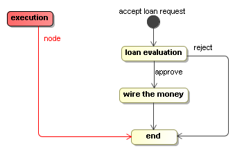
In this next example, we'll combine automatic activities and wait states. This example is a simplified version of a loan approval process. Graphically, it looks like this:
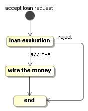
Building process graphs in Java code can be tedious because you have to keep track of all the references in local variables. To resolve that, the Process Virtual Machine comes with a ProcessFactory. The ProcessFactory is a kind of domain specific language (DSL) that is embedded in Java and eases the construction of process graphs. This pattern is also known as a fluent interface.
ProcessDefinition processDefinition = ProcessFactory.build()
    .node("accept loan request").initial().behaviour(new WaitState())
      .transition().to("loan evaluation")
    .node("loan evaluation").behaviour(new WaitState())
      .transition("approve").to("wire the money")
      .transition("reject").to("end")
    .node("wire the money").behaviour(new Display("automatic payment"))
      .transition().to("end")
    .node("end").behaviour(new WaitState())
.done();
For more details about the ProcessFactory, see the javadocs. An alternative for the ProcessFactory would be to create an XML language and an XML parser for expressing processes. The XML parser can then instantiate the classes of package org.jbpm.pvm.impl directly. That approach is typically taken by process languages.
The node wire the money is an automatic node. The Display implementation uses the Java API's to just print a message to the console. But the witty reader can imagine an alternative Activity implementation that uses the Java API of a payment processing library to make a real automatic payment. All the other nodes are wait states.
A new execution for the process above can be started like this
Execution execution = processDefinition.startExecution();
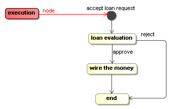
Starting a new execution implies that the initial node is executed. Since in this case it's a wait state, the new execution will be positioned in the node 'accept loan request' when the startExecution-method returns.
Now we can give this execution an external trigger with the signal- method on the execution. Invoking the signal method will take the execution to the next wait state.
execution.signal();
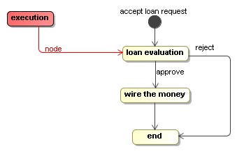
Now, the execution is at an interesting point. There are two transitions out of the state 'loan evaluation'. One transition is called 'approve' and one transition is called 'reject'. As we explained above in the WaitState implementation, the transition taken corresponds to the signal that is given. Let's feed in the 'approve' signal like this:
execution.signal("approve");The 'approve' signal will cause the execution to take the 'approve' transition and it will arrive in the node 'wire the money'.
In wire the money, the message will be printed to the console. Since, the Display activity didn't invoke the execution.waitForSignal(), nor any of the other execution propagation methods, the default behaviour will be to just proceed.
Proceeding in this case means that the default outgoing transition is taken and the execution will arrive in the end node, which is a wait state.
So only when the end wait state is reached, the signal("approve") returns. That is because all of the things that needed to be done between the original state and this new state could be executed by the process system. Executing till the next wait state is the default behaviour and that behaviour can be changed with
TODO: add link to async continuations
asynchronous continuations in case transactions should not include all calculations till the next wait state. For more about this, see Section 4.4, “Execution and threads”.
Another signal invocation will bring it eventually in the end state.
There are basically two forms of process languages: graph based and composite process languages. First of all, this design supports both. Even graph based execution and node composition can be used in combination to implement something like UML super states.
In this design, control flow activity implementations will have to be aware of whether they are dependent on transitions (graph based) or whether they are using the composite node structure. The goal of this design is that all non-control flow activities can be implemented in the same way so that you can use them in graph based process languages as well as in composite process languages.
Events are points in the process definition to which a list of activities can be subscribed as listeners. The motivation for events is to allow for developers to add programming logic to a process without changing the process diagram. This is a very valuable instrument in facilitating the collaboration between business analysts and developers. Business analysts are responsible for expressing the requirements. When they use a process graph to document those requirements, developers can take this diagram and make it executable. Events can be a very handy to insert technical details into a process (like e.g. some database insert) in which the business analyst is not interested.
Most common events are fired by the execution automatically:
- Transition.EVENT_TRANSITION_TAKE = "transition-take" : fired on transitions when transitions are taken.
- Node.EVENT_NODE_ENTER = "node-enter" : fired on the node when execution enters that node. This happens when execution takes a transition to that node, when a child node is being executed with execution.execute(Node) or when a transition is taken from a node outside that node to a contained node. The latter refers to super states in state machines.
- Node.EVENT_NODE_LEAVE = "node-leave" : fired on the node when a transition is taken out of that node or when a child node execution is finished and the execution is propagated to the parent node.
- ProcessDefinition.EVENT_PROCESS_START = "process-start" : fired on a process when a new process is started.
- ProcessDefinition.EVENT_PROCESS_END = "process-end" : fired on a process when a new process is ended. This might include a executions that are ended with a cancelled or error state.
Events are identified by the combination of a process element and an event name. Users and process languages can also fire events programmatically with the fire method on the Execution:
public interface Execution extends Serializable {
  ...
  void fire(String eventName, ProcessElement eventSource);
  ...
}
A list of Activitys can be associated to an event. But activities on events can not influence the control flow of the execution since they are merely listeners to an execution wich is already in progress. This is different from activities that serve as the behaviour for nodes. Node behaviour activities are responsible for propagating the execution. So if an activity in an event invokes any of the following methods, then it will result in an exception.
- waitForSignal()
- take(Transition)
- end(*)
- execute(Node)
We'll reuse the Display activity from above in a simple process: two nodes connected by a transition. The Display listener will be subscribed to the transition event.
ProcessDefinition processDefinition = ProcessFactory.build()
    .node("a").initial().behaviour(new WaitState())
      .event("node-leave")
        .listener(new Display("leaving a"))
        .listener(new Display("second message while leaving a"))
      .transition().to("b")
        .listener(new Display("taking transition"))
    .node("b").behaviour(new WaitState())
      .event("node-enter")
        .listener(new Display("entering b"))
.done();
The first event shows how to register multiple listeners to the same event. They will be notified in the order as they are specified.
Then, on the transition, there is only one type of event. So in that case, the event type must not be specified and the listeners can be added directly on the transition.
A listeners will be called each time an execution fires the event to which the listener is subscribed. The execution will be provided in the activity interface as a parameter and can be used by listeners except for the methods that control the propagation of execution.
Events are by default propagated to enclosing process elements. The motivation is to allow for listeners on process definitions or composite nodes that get executed for all events that occur within that process element. For example this feature allows to register a listener on a process definition or a composite node on node-leave events. Such action will be executed if that node is left. And if that listener is registered on a composite node, it will also be executed for all nodes that are left within that composite node.
To show this clearly, we'll create a DisplaySource activity that will print the message leaving and the source of the event to the console.
public class DisplaySource implements Activity {

  public void execute(Execution execution) {
    System.out.println("leaving "+execution.getEventSource());
  }
}
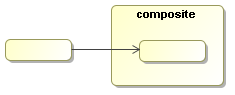
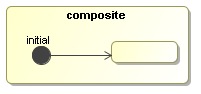
Note that the purpose of event listeners is not to be visible, that's why the activity itself should not be displayed in the diagram. A DisplaySource activity will be added as a listener to the event node-leave on the composite node.
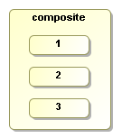
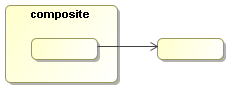
The next process shows how the DisplaySource activity is registered as a listener to to the 'node-leave' event on the composite node:
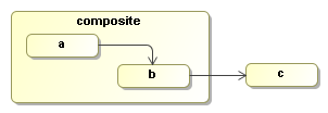
ProcessDefinition processDefinition = ProcessFactory.build("propagate")
    .compositeNode("composite")
      .event(Node.EVENT_NODE_LEAVE)
        .listener(new DisplaySource())
      .node("a").initial().behaviour(new WaitState())
        .transition().to("b")
      .node("b").behaviour(new WaitState())
        .transition().to("c")
    .compositeEnd()
    .node("c").behaviour(new WaitState())
.done();
Next we'll start an execution.
Execution execution = processDefinition.startExecution();
After starting a new execution, the execution will be in node a as that is the initial node. No nodes have been left so no message is logged. Next a signal will be given to the execution, causing it to take the transition from a to b.
execution.signal();
When the signal method returns, the execution will have taken the transition and the node-leave event will be fired on node a. That event will be propagated to the composite node and to the process definition. Since our propagation logger is placed on node composite it will receive the event and print the following message:
leaving node(a)
Another
execution.signal();
will take the transition from b to c. That will fire two node-leave events. One on node b and one on node composite. So the following lines will be appended to the console output:
leaving node(b)
leaving node(composite)
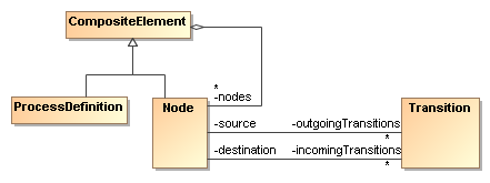
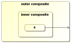
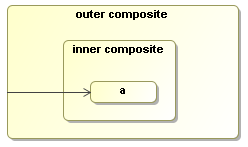
Event propagation is build on the hierarchical composition structure of the process definition. The top level element is always the process definition. The process definition contains a list of nodes. Each node can be a leaf node or it can be a composite node, which means that it contains a list of nested nodes. Nested nodes can be used for e.g. super states or composite activities in nested process languages like BPEL.
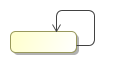
So the even model also works similarly for composite nodes as it did for the process definition above. Suppose that 'Phase one' models a super state as in state machines. Then event propagation allows to subscribe to all events within that super state. The idea is that the hierarchical composition corresponds to diagram representation. If an element 'e' is drawn inside another element 'p', then p is the parent of e. A process definition has a set of top level nodes. Every node can have a set of nested nodes. The parent of a transition is considered as the first common parent for it's source and destination.
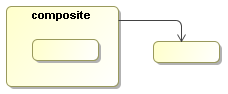
If an event listener is not interested in propagated events, propagation can be disabled with propagationDisabled(). The next process is the same process as above except that propagated events will be disabled on the event listener. The graph diagram remains the same.
Building the process with the process factory:
ProcessDefinition processDefinition = ProcessFactory.build("propagate")
    .compositeNode("composite")
      .event(Node.EVENT_NODE_LEAVE)
        .listener(new DisplaySource())
        .propagationDisabled()
      .node("a").initial().behaviour(new WaitState())
        .transition().to("b")
      .node("b").behaviour(new WaitState())
        .transition().to("c")
    .nodesEnd()
    .node("c").behaviour(new WaitState())
.done();
So when the first signal is given for this process, again the node-leave event will be fired on node a, but now the listener on the composite node will not be executed cause propagated events have been disabled. Disabling propagation is a property on the listener and doesn't influence the other listeners. The event will always be fired and propagated over the whole parent hierarchy.
Execution execution = processDefinition.startExecution();
execution.signal();
Next, the second signal will take the transition from b to c.
execution.signal()
Again two node-leave events are fired just like above on nodes b and composite respectively. The first event is the node-leave event on node b. That will be propagated to the composite node. So the listener will not be executed for this event cause it has propagation disabled. But the listener will be executed for the node-leave event on the composite node. That is not propagated, but fired directly on the composite node. So the listener will now be executed only once for the composite node as shown in the following console output:
leaving node(composite)
Above we already touched briefly on the two main process constructs: Nodes, transitions and node composition. This section will elaborate on all the basic combination possibilities.