A Choreography represents the description of how multiple participants (or roles) interact to achieve a goal.
In a Service Oriented Architecture context, it provides a service neutral view of a complete architecture, documenting how the services should communicate with each other in a peer-to-peer manner. This description can be used to understand the complete process at a higher level, and then used to generate initial template service designs (or implementations) for each of the participants within the choreography.
The BPMN standard has been around for some time, although it was focused on providing a standard notation for describing business processes.
In 2011 a major new version of the standard was created under the OMG with the following goals:
provide a standard meta-model, to support interchange
define execution semantics for the process model
add a choreography model to the existing process and collaboration models
The BPMN2 Choreography can be created using the Eclipse BPMN2 modeller that is bundled with the Savara Eclipse tooling, as well as being available from: http://eclipse.org/projects/project.php?id=soa.bpmn2-modeler
To create a BPMN2 Choreography, select the “New->Other...” menu item on the context menu for the project or folder that will contain the file, which will display the following dialog:
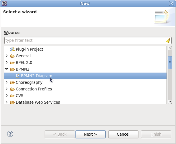
Select the “BPMN2 Diagram” under the BPMN2 category and press the Next button.
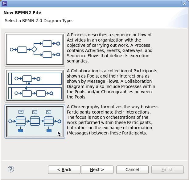
As we wish to create a choreography, you should now select the bottom button and press the Next button.
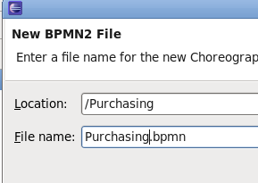
The final step in creating the diagram is to name it, and then press the Finish button.
Once the diagram has been created, it is useful to establish any XSD schemas (with their namespaces and prefixes) before making use of them when building the diagram.
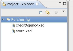
In this example, we copy two existing schema files into the newly created project.
NOTE: Normally this information can be established on the fly when specifying the item definition, but currently does not work, so needs to be done as a separate step. So could possibly remove this step when this feature is available again.
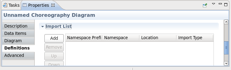
Open the Properties view and select the diagram background. Then select the 'Definitions' tab (as shown in the image) and scroll down to the Import List section. Pressing the 'Add' button will show the following dialog:
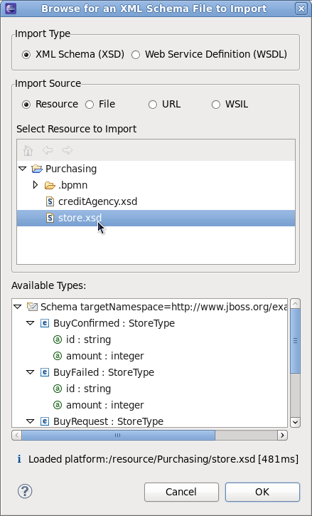
Locate the XSD schema file(s) and press the OK button. Although in this case we have two schemas within the project, it is possible for the schemas to be located using a few different mechanisms.
NOTE: URL location does not seem to work currently – and it would also be useful to define an import for a namespace/prefix that does not have an associated schema, as the location is optional.
When a Choreography Diagram is initially created, it will create a default Choreography Task. It is possible to simply change this information as the starting point for your diagram, but for the purposes of this article we will create a choreography task from scratch – so select this default choreography task and delete it.
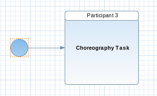
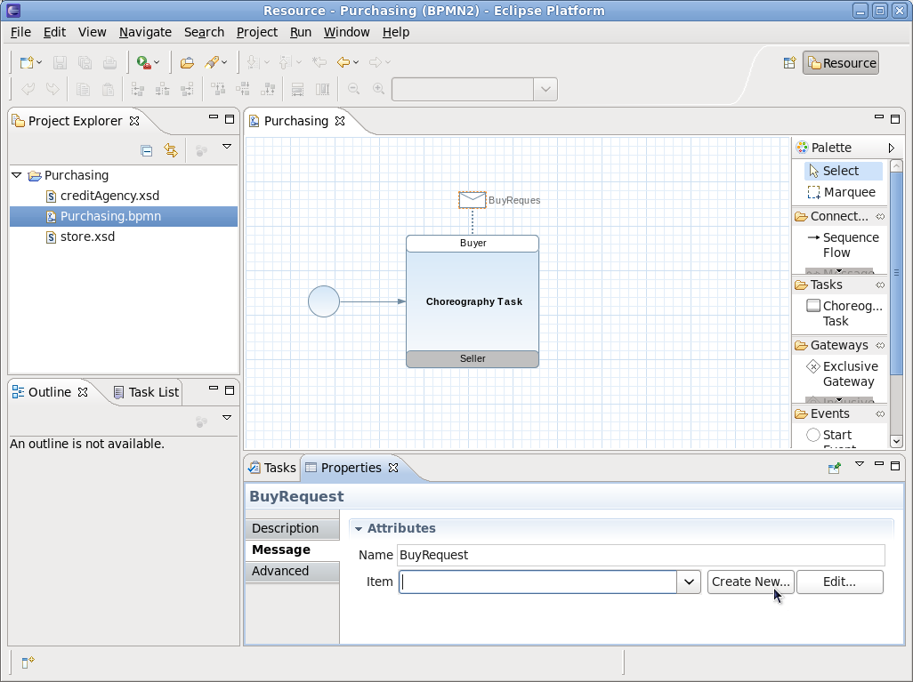
Components to be included in the Choreography Diagram are provided in the palette on the right hand side of the canvas. We initially want to start the diagram with a “Start Event”, a “Choreography Task” and a “Sequence Flow” to connect the two. This should then look like this....
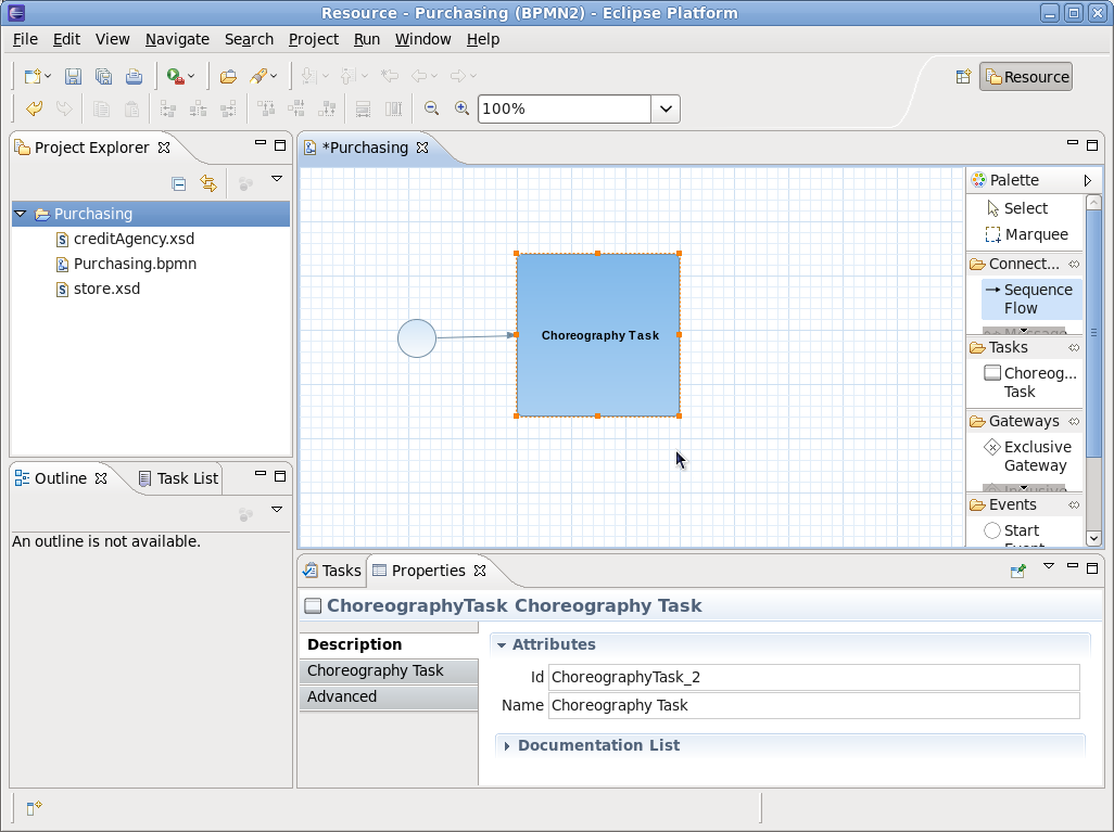
The Properties view will show the details for the newly create Choreography Task, allowing you to change its name to something that reflects what it represents, e.g. “Submit Purchase Order”.
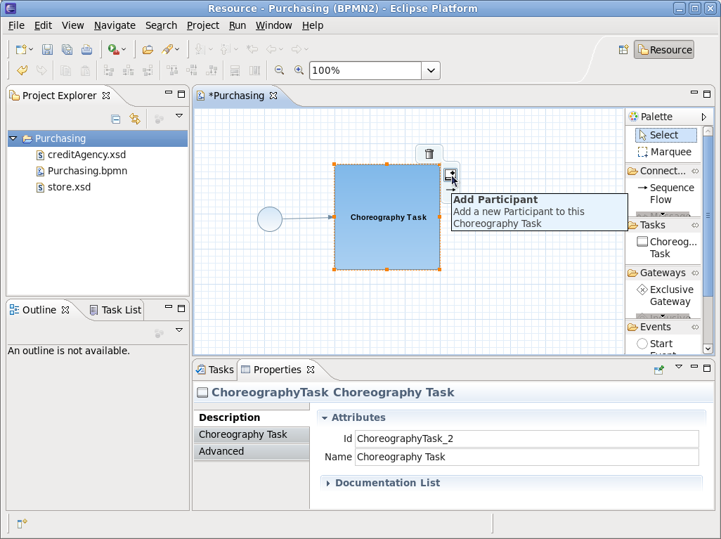
The next step is to establish the Participants that will be performing the interaction associated with the Choreography Task. As shown in the diagram, the Choreography Task has a short cut button (also available via its context menu) to add a participant.
When this button is pressed, it will add a new participant to the task, or if available, also present a list of existing participants that can be selected. The first participant added to the choreography task will be considered the 'initiating participant', which means it will send the message. If two messages are associated with the same choreography task (e.g. representing a request/response pattern), then the initiator sends the request, and the other participant would return the response. In general, only associate two messages with a choreography task if the associated 'operation' will only have the single response type. If it has multiple response types (e.g. one normal and one or more faults), then separate choreography tasks should be used – as will be seen later in the purchasing example.
When the participant band has been added to the choreography task, it can be selected to focus the Properties view on its properties. The name can then be changed to something more meaningful, for example Buyer. The following image shows the task after both participants have been added and their names changed.
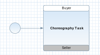
Figure 3.10. Participants given names using the Properties view when focusing on the participant band
Now that we have defined the choreography task to represent an interaction from the Buyer to the Seller, we now need to describe the message that will be passed between them.
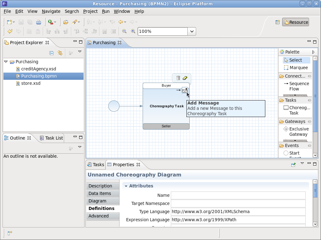
As with adding participants, there is a short cut button (and context menu item) for adding a message, associated with the participant band that is sending the message. So in the image above, adding a message to the Buyer would define the request, as the Buyer is the initiator for this task (denoted by its white background).
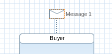
As with the 'Add Participant' action, if there are existing message definitions, then these will be presented to the user to enable them to select a previously defined message. Otherwise a message icon will simply be added.
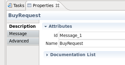
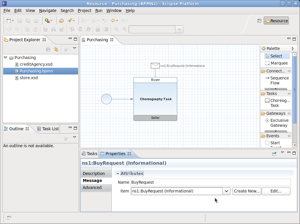
The user can now select this message 'envelope' to view its properties and set its name, e.g. “BuyRequest”.
However the BuyRequest name is only a logical name, it does not define the details of the message structure. This is ok when we are simply sketching the high level representation of a choreography, but to enable the choreography to represent concrete details, we need to associate the message with an item definition.
In the Properties view associated with the selected message there is an 'Item' field. This allows the user to select a previously defined message type (e.g. from an imported XSD schema), or if an appropriate entry does not exist, then we can press the 'Create New' button.
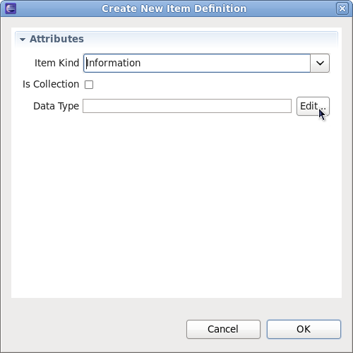
The 'Item Kind' field will always be 'Information', unless defining some abstract choreography describing how physical items are exchanged. The 'Data Type' field references the detailed message schema type. To set the field, press the 'Edit...' button and set the value:
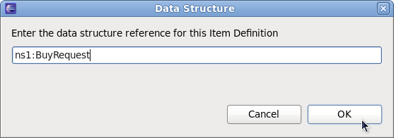
NOTE: Currently this only enables a free format string value to be defined – but should bring up the import dialog and enable the user to select a specific type, creating the import entry on the fly if necessary.
Now that the message details have been provided, the diagram displays that information in place of the logical message name.
NOTE: Currently does not actively update after this information is set – or when the message name is changed (when no item definition set).
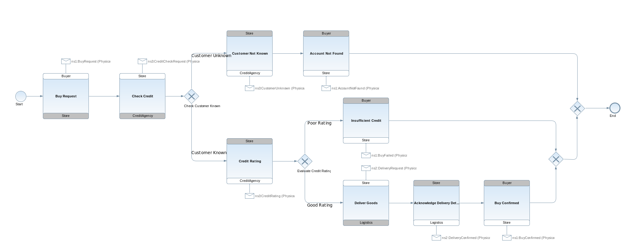
Using the same steps as defined above, each of the choreography tasks can be created, and with a couple of decision points we end up with the following business process.....
NOTES: Currently shows item definition kind as 'physical' – default is 'information'.
Although the choreography diagram (and underling model) now shows how messages are exchanged by participants in the choreography, these exchanges have not been defined in an SOA context, based on service interfaces. Therefore we also need to define (within the model) how these message exchanges are grouped into message exchange patterns (MEP) on interfaces associated with the participants.
Although this can be achieved by adding Interface and Operation components within the model, and establishing the appropriate associations from the participants to the interfaces, there is a short cut that will derive this information from the interactions in the model.
However before invoking this utility, we have one final step that needs to be done. In the preceding sections you have seen how to create messages and exchange them between participants as part of a Choreography Task. Although this is adequate information from a message passing perspective, as it defines a reference to the specific message schema that is used, it does not indicate whether the message exchange represents a fault associated with a preceding request.
Therefore it is necessary to distinguish whether a particular message type is actually a fault (or error), to enable the service interface derivation to correctly distinguish between normal and fault responses in a service operation.
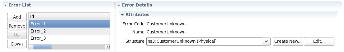
For each message type that needs to be highlighted as a fault, we need to create an Error component that references the same item definition. This Error component will essentially define the fault code for the fault, which will be used when constructing the RPC operation signature.
Select the Data Items tab, from the Properties associated with the diagram canvas, and expand the Error List :
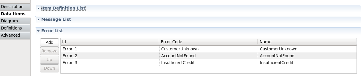
Using the 'Add' button, create a new entry and configure its details to reference the required item definition (representing the message schema) and error code:
Once all of the required Error components have been created and configured, then select the " Savara->BPMN2->Add Service Interfaces " menu item, associated with the BPMN2 choreography file, to create the appropriate interfaces and establish the necessary relationships.
The Choreography represents an overall description of the architecture intended to support a set of scenarios that define the business requirements.
Therefore, to ensure that the choreography correctly reflects those business requirements, it is import that we can verify the choreography against those scenarios.
As described in the previous Scenarios chapter, each scenario can be simulated against the choreography, to statically verify that the choreography addresses all of the use cases outlined in the scenarios.Once the choreography successfully verifies against each of the scenarios, it can then be deemed to represent the business requirements, and then be used to generate further service related artifacts.